Do you have a question about the Intergas ECO RF 24 and is the answer not in the manual?
Covers critical safety warnings, installation compliance, and warranty implications for incorrect installation or re-registration.
Provides guidance on safe and ergonomic practices for lifting and moving the boiler to prevent injury.
Details specific handling and storage instructions for the appliance packaging to ensure safe transport and storage.
Lists contact information for Intergas Heating Ltd for technical assistance, installation, maintenance, and repair work.
Explains where to find appliance data on the data plate and lists key identification details found on it.
Outlines legal requirements for gas appliance installation by competent engineers and adherence to building regulations.
Details compliance with British Standards codes of practice for appliance installation, including flues, ventilation, and hot water systems.
Lists the product's approvals, including British Gas Service Listing and Notified Body details.
Provides comprehensive technical specifications for the Combi Compact ECO RF range, including performance and dimensions.
Identifies and labels the various components of the Intergas Combi Compact ECO RF boiler with a detailed diagram.
Describes the electronic control unit responsible for ignition, flame supervision, and gas supply modulation.
Explains the integral high efficiency pump and its function in circulating water through the heat exchanger and CH circuit.
Details the use of external programmable thermostats and the integrated RF module for wireless room thermostat control.
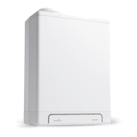
Introduces the boiler as a modulating high efficiency unit with independent CH and DHW circuits, prioritizing hot water.
Describes how the boiler operates in central heating mode, adjusting output based on demand and pump circulation.
Explains the boiler's operation for domestic hot water, prioritizing DHW demand and temporarily stopping the CH pump.
Details the various operating modes indicated by codes on the service display, including Off and Waiting modes.
Describes the interface for PC connection using diagnostic software for monitoring boiler controller and installation behavior.
Explains how to activate test modes for checking burner operation at minimum and maximum power settings.
Details the internal frost protection mechanism and the requirement for external frost thermostats in freezing conditions.
Provides detailed diagrams and measurements for the appliance and its wall mounting jig, including connection sizes.
Provides recommended clearances, ventilation requirements, and considerations for installing the boiler in various locations, including kitchen cupboards.
Details the methods for mounting the boiler using the supplied fixing strip or a wall mounting jig with an expansion vessel.
Guides through unpacking, checking contents, fitting the appliance, condensate trap, and flue system.
Instructs on flushing the CH system, fitting pipes, and equipping the system with necessary components like drain taps.
Covers flushing the DHW installation, connecting pipes, notes on usage, flow resistance, and minimum water pressure requirements.
Details electrical safety precautions and provides connection diagrams for various controls like room thermostats and sensors.
Explains the connection of the condensate trap to the drain, material requirements, gradient, and frost prevention measures.
Covers flue pipe types, air supply, terminal positions, system lengths, horizontal and vertical flue installations, and plume management.
Guides on filling and venting the CH system, checking connections, and performing a self-test for the appliance.
Details checks required for combustion integrity, flue system, and operational gas inlet pressure before appliance operation.
Emphasizes correct flue system connection, checking flue termination, and procedures if visual inspection access is restricted.
Provides step-by-step instructions for starting up the appliance, adjusting pump settings, and checking heating/hot water operation.
Details the procedure for safely shutting down and draining the appliance and installation, especially if freezing is possible.
Explains how to operate functions like appliance on/off, DHW comfort settings, and reset the appliance via the control panel.
Guides on accessing and modifying boiler parameters using the service code, including activating program memory.
Lists and describes various parameters affecting boiler operation, with their factory settings and adjustment ranges.
Details how to adjust the maximum central heating power by changing fan speed settings, with a power vs. speed table.
Explains how to adjust the pump speed based on installation resistance and set maximum power, checking temperature differences.
Describes how to automatically adjust supply temperature based on outside temperature using a connected external sensor.
Provides procedures for checking CO2 percentages at maximum and minimum power, detailing test programs and required values.
Guides on adjusting the CO2 setting at minimum power using the adjustment screw on the gas valve.
Details the procedure for converting the appliance to a different gas type, including replacing the gas restriction and checking settings.
Lists fault codes indicated on the main display when the boiler controller detects a fault, with possible solutions.
Troubleshooting guide for common issues like burner ignition problems, noisy operation, and lack of heating or hot water.
Provides step-by-step instructions for safely dismantling the boiler, including removing the front panel and flue pipe.
Details the cleaning procedures for the heat exchanger, condensate drain pan, and condensate trap.
Guides on correctly reassembling the boiler after maintenance, including fitting seals, connections, and the front cover.
Outlines essential checks for combustion performance, flue system integrity, and gas inlet pressure during routine servicing.
Presents the complete electrical wiring diagram for the boiler, identifying components and connection terminals.
Provides a table of NTC thermistor resistances at various temperatures for diagnostic purposes.