What should I do if my Intergas Combi Compact HRE 28/24 shows a sensor fault after a self check?
- JjonathanhansenSep 12, 2025
If your Intergas Boiler displays a sensor fault after a self-check, replace S1 and/or S2.
What should I do if my Intergas Combi Compact HRE 28/24 shows a sensor fault after a self check?
If your Intergas Boiler displays a sensor fault after a self-check, replace S1 and/or S2.
Why is there no heating (CH) in my Intergas Combi Compact HRE 28/24 Boiler?
If your Intergas Boiler isn't providing heat, consider the following troubleshooting steps: * Replace the thermostat if it's faulty. * Check the wiring against the diagram. * Check the connector X4 if there's no current (24 V). * Replace the faulty manager. * Check the power supply at connector X2. * Replace the faulty pump if it's not running. * Replace sensor S1 or S2 if the burner isn't firing on CH. See fault code. * Refer to the 'burner does not ignite' section if the burner isn't igniting.
Why does my Intergas Boiler burner ignite noisily?
If your Intergas Boiler's burner ignites noisily, it could be due to several reasons: * The gas supply pressure might be too high. The house pressure switch may be faulty; contact the gas company. * The ignition electrode gap may be incorrect; check the ignition electrode gap. * The gas/air adjustment may not be correctly set; check the setting (refer to gas/air adjustment guidelines). * There might be a weak spark; the spark gap should be approximately 4.5 mm.
Why is my Intergas Combi Compact HRE 28/24 not producing hot water (DHW)?
If your Intergas Boiler is not providing hot water, consider the following: * Replace the flow switch if the DHW flow is less than 2.0 l/min. * Check the wiring according to the diagram if there's no current at the flow switch (5V DC). * Replace S3 if the burner isn't firing on DHW. * Refer to the 'burner does not ignite' section if the burner isn't igniting.
Why is the burner resonating in my Intergas Boiler?
If your Intergas Boiler's burner is resonating, consider these potential causes: * The gas supply pressure may be too low. The house pressure switch may be faulty; contact the gas company. * There might be recirculation of combustion gasses; check the gas flue and the air supply. * The gas/air adjustment might not be correctly set; check the setting (refer to gas/air adjustment guidelines).
Why does the hot water from my Intergas Combi Compact HRE 28/24 Boiler not reach temperature?
If your Intergas Boiler's hot water isn't reaching the desired temperature, consider the following: * Adjust the inlet assembly if the DHW flow is too high. * Set the hot water circuit depending on the desired temperature, if the temperature setting for the water circuit is too low. * Descale or flush the exchanger DHW side if there's no heat transfer due to lime scale or fouling in the heat exchanger DHW side.
What to do if the gas valve relay is faulty in Intergas Boiler?
If the gas valve relay is faulty in your Intergas Boiler, replace the boiler controller.
What to do if the temperature is too high in Intergas Combi Compact HRE 28/24?
If your Intergas Boiler is overheating, possible solutions include: * Removing air from the installation. * Ensuring the pump is running. * Verifying sufficient flow in the installation, checking that radiators are open, and ensuring the pump setting isn't too low. * Checking if the flow switch is sticking.
How to restore power if it's reduced in Intergas Combi Compact HRE 28/24?
If your Intergas Boiler's power is reduced, check the appliance and flue system for fouling and clean them.
What to do if my Intergas Combi Compact HRE 28/24 Boiler displays sensor fault S2?
If your Intergas Boiler displays a sensor fault S2, check the wiring for any breaks and replace S2 if necessary.
Details the statutory instruments and directives the boiler complies with.
Covers general warnings regarding installation, performance, and guarantee implications.
Provides guidance on safe methods for lifting and moving the boiler unit.
Lists important handling and storage precautions indicated on the product packaging.
Explains the meaning of various safety and warning symbols used throughout the manual.
Defines common abbreviations and technical terms used in the manual for clarity.
Guides the user on how to use the manual for assembly, installation, and maintenance.
Provides contact information for Intergas Heating Ltd for technical assistance and support.
Explains where to find and what information is available on the appliance's data plate.
Outlines legal requirements for gas appliance installation by Gas Safe registered engineers.
Specifies compliance with British Standards codes of practice for installation.
Lists the approvals and directives the boiler range meets, including G.C. numbers.
Presents detailed technical specifications for different models of the Combi Compact HRE.
Provides product fiche information according to CELEX-32013R0811, ANNEX IV.
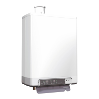
Illustrates and labels the various components of the boiler unit.
Describes the Intergas Combi Compact HRE boiler as a closed appliance for heating and DHW.
Explains the function of the electronic control unit for burner ignition and flame supervision.
States that all boiler adjustments are accessible through the parameter list.
Details the heat transfer process via a hermetically sealed combustion chamber.
Describes the integral pump and circulation for the central heating circuit.
Explains that room temperature is controlled by an external thermostat.
Details the boiler's integrated clock for setting heating periods and displaying status.
Describes the boiler as a modulating high efficiency unit with independent CH and DHW circuits.
Explains the process when a heating demand is requested, including pump and burner operation.
Describes the automatic firing of the boiler for hot water requests, prioritizing DHW.
Details the codes displayed for different operating modes like 'Off' and 'Waiting mode'.
Explains the boiler's digital clock for programming heating periods and special modes.
Describes the interface for PC connection using special software for monitoring.
Details how to activate test programs for appliance operation at fixed fan speeds.
Explains the internal frost protection mechanism and the need for external thermostats.
Provides diagrams and measurements for appliance dimensions and connections.
Specifies requirements for siting the boiler, including clearances and ventilation.
Details the methods for mounting the boiler using a wall mounting jig or fixing strip.
Outlines the steps for unpacking, checking, and physically installing the boiler unit.
Instructions for connecting the central heating system, including flushing and pipework.
Lists essential components for the CH system, such as drain taps and non-return valves.
Notes the requirement for an auto bypass when using thermostatic radiator valves.
Provides guidance on connecting floor heating systems to avoid undesired circulation.
Details the process for connecting the domestic hot water installation, including flushing.
Provides important notes on using the appliance solely for hot water or during winter shutdown.
Presents a graph illustrating flow resistance for different boiler models in the DHW circuit.
Specifies the minimum required mains water pressure for correct DHW operation.
Details the procedures and precautions for making electrical connections to the boiler.
Provides a table for various electrical connections to connectors X4 and X2.
Explains how to connect a low voltage on/off room thermostat to connector X4.
Details the connection for an Open Therm thermostat to enable communication.
Describes the connection of an outside temperature sensor for weather-dependent regulation.
Explains the connection of a 230V AC room thermostat to connector X2.
Covers external controls for time/temperature and DHW cylinders or CH zones.
Provides instructions and precautions for connecting the condensate discharge system.
Details the requirements for the flue system, including pipe adapters and air supply.
Specifies the use of approved Intergas flue products and the concentric flue adapter.
Lists minimum distances for flue terminals based on their position relative to openings.
Provides tables for maximum flue pipe lengths and air inlet configurations.
Describes the extension of the horizontal flue system and requirements for bends and falls.
Details the availability and extension of the vertical flue system kit.
Explains the components and installation of the plume management kit for flue terminals.
Covers requirements for flue systems installed in voids, including inspection and access.
Step-by-step guide for filling and venting the CH system, hot water supply, and gas supply.
Specific instructions for filling and venting the central heating system, including safety cautions.
Procedure for venting the heat exchanger and pipe system via a hot water tap.
Instructions for checking gas supply pressure and performing operational checks.
Covers checking and adjusting combustion settings, including flue gas analysis.
Ensures the flue system is correctly connected and terminated as per manufacturer's instructions.
Details the procedure for starting up and commissioning the boiler after installation.
Explains how to set the clock and timer functions for heating periods.
Step-by-step guide to setting the 24-hour clock and adjusting the time.
Describes how to set the on/off times for central heating periods.
Details how to activate temporary or continuous 'on' modes for heating demands.
Provides instructions for safely shutting down the appliance and draining the system.
Explains functions that can be operated directly from the boiler's control panel.
Details how to start and stop the appliance using the power button.
Describes the DHW comfort function settings: On, Eco, and Off.
Explains how to reset the appliance after a lock-out using the reset button.
Guides on how to enter the user settings menu and change parameter values.
Details how to set the maximum central heating supply temperature.
Explains how to adjust the domestic hot water temperature setting.
Instructions for accessing and changing parameters using the installer service code.
Lists all adjustable parameters, their factory settings, and descriptions for Combi Compact HRE.
Explains how to control the keep hot facility using an Open Therm thermostat.
Details how to adjust weather compensation using an external sensor and heating lines.
Explains how to adjust the maximum central heating power by changing fan RPM.
Guides on adjusting the pump setting based on maximum power and water resistance.
Covers the factory setting of the gas-air ratio and conversion to different gas types.
Details procedures for checking flue gas at maximum and minimum output.
Step-by-step guide to measuring flue gas O2 or CO2 at maximum appliance output.
Procedure for measuring flue gas O2 or CO2 at minimum appliance output.
Explains how to adjust the gas air ratio on minimum power using the gas valve setting screw.
Provides instructions for converting the boiler to a different gas type, including gas restriction replacement.
Details the process of replacing the O-ring and gas restriction for gas conversion.
Lists fault codes indicated on the display, their meaning, and possible solutions.
Covers common faults like burner not igniting, noisy ignition, or burner resonating.
Troubleshooting steps for when the burner fails to ignite.
Addresses causes and solutions for noisy burner ignition.
Covers potential causes and solutions for burner resonating issues.
Troubleshooting steps for no heat output in the central heating system.
Addresses issues where the appliance's power output is reduced.
Troubleshooting steps for when the central heating does not reach the set temperature.
Troubleshooting steps for when there is no hot water supply.
Steps to resolve issues where hot water temperature is insufficient.
Troubleshooting for the CH pump LED flashing red and green alternately.
Troubleshooting for the CH pump LED flashing red, indicating pump not running.
Provides instructions and cautions for disassembling boiler components.
Details the procedures for cleaning the heat exchanger, condensate drain pan, and trap.
Guides on correctly reassembling the boiler components after maintenance or repair.
Covers essential checks for combustion integrity during routine servicing.
Presents the main electrical wiring diagram and component connections.
Provides a table of NTC resistances at various temperatures for sensor diagnostics.
| Type | - |
|---|---|
| Fuel type | Natural gas |
| Boiler system | Combi boiler system |
| Product color | White |
| Heater location | Indoor |
| Placement supported | Vertical |
| Gas inspection label | CW, HRe, NZ, SV |
| Boiler type (NL label) | HR |
| CW inspection label class | 4 |
| HR inspection label class | 107 |
| Efficiency | 107 % |
| Maximum power | - W |
| Water flow (40 °C) | 12.5 l/min |
| Water flow (60 °C) | 7.5 l/min |
| Maximum operating pressure | 3 bar |
| Domestic Hot Water (DHW) flow | - l/min |
| Depth | 240 mm |
|---|---|
| Width | 450 mm |
| Height | 650 mm |
| Weight | 33000 g |






 Loading...