Interklima Terminal Units
PCE -VS ñ Hydronic cassette
34
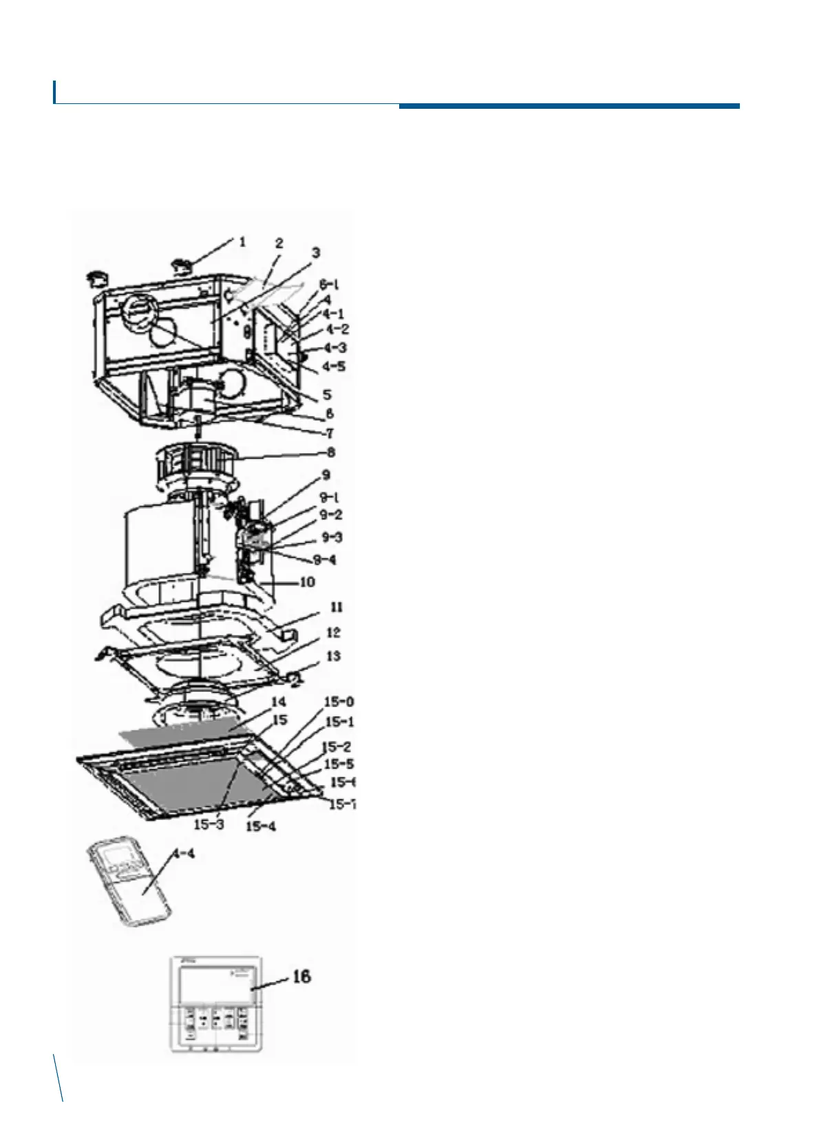
Exploded view drawing
PCE-03/04/06/08-VS
1- Mounting brackets
2- External drain pan
3- Casing
4- Control box
4-1- Main PCB
4-2- Transformer
4-3- Terminal block
4-4- Remote handset
4-5- Wire clip
5- Branch duct
6- Fan motor (for PCE-03-04)
6- Fan motor (for PCE-06)
6- Fan motor (for PCE-08)
6-1- Motor capacitor (for PCE-03-04)
6-1- Motor capacitor (for PCE-06-08)
7- Fresh air outlet
8- Fan blower
9- Drain pump assembly
9-1- Drain pump fixture
9-2- Drain pump
9-3- Drainage tube
9-4- Float switch
10- Coil (PCE-03-04)
10- Coil (PCE-06-08)
11- Drain pan
12- Drain pan fixture
13- Venturi
14- Air filter
15- Cover panel assembly
15-0- Receiver display
15-1- Receiver label sticker
15-2- Grille
15-3- Bolt (Left)
15-4- Bolt (Right)
15-5- Swing Louver
15-6- Stepping motor
15-7- Fan bearing
16- Wired wall pad