8 3 9 4 g 0 9 b . d s f
1
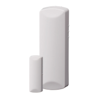
/HDUQ0RGH6KRFN
6HQVRU
ITI Part No. 60-886-95
60-886-11-95
Installation Instructions
Product Summary
The Learn Mode Shock Sensor has the following three main
functions:
❑ To detect the vibrations made by an intruder trying to
break a window or door.
❑ To detect a window or door opening.
❑ To detect tamper situations, such as an intruder remov-
ing the sensor cover.
Vibrations cause a momentary open circuit in the shock ele-
ment of the sensor. The circuit closes again when the vibra-
tion stops. The sensor microcontroller “sees” the open/close
action as a pulse, causing the sensor to transmit an alarm
signal. The sensor has two different detection modes:
❑ Gross Attack - detect a violent blow sufficient in length
to trip sensor.
❑ Pulse Count - detect a sufficient number of less violent
blows (rapping or tapping).
The sensor includes an internal magnetic reed switch that
must be disabled if it is not used.
A cover tamper provides additional security if an intruder
tries to disable or damage the sensor.
Figure 1. Shock Sensor Main Components
Installation Guidelines
❑ Learn the sensor before adjusting the shock sensitivity.
The sensor is shipped with the reed switch enabled and
open, and this is how it must be learned.
❑ Before permanently mounting the sensor, test it at the
intended location to make sure that the panel can
receive sensor signal transmissions. The sensor is an
RF device and there may be blind or non-operational
locations within the installation. Normally, these can be
overcome by moving the sensor or receiver.
❑ Always mount the shock sensor so that the detector is
on the frame and not on glass, solid, or hollow-core
doors. See Figure 2 for mounting locations.
Figure 2. Mounting Options for Door/Window Styles
❑ Mount the sensor in a location where the structure can
transmit vibrations to the sensor.
❑ The sensor can be mounted on a vertical surface or on a
horizontal (flat) surface.
❑ Make sure the window fits snugly in the frame and
doesn’t move or rattle.
❑ Hold the sensor against the frame to make sure the sen-
sor base fits on the surface area of the frame and
doesn’t extend over the surface edges.
Shock Sensor Orientation
There are two types of shock sensor mounting orientations;
on a vertical surface or on a horizontal surface (sill or
ledge).
On a vertical surface, there are two orientations (see Figure
3).
Note
On a vertical surface, the shock sensor element must
always be oriented with its screw terminals down
, or the
writing on the shock element horizontal.
1 2 3 4 5 6
O N
Reed
Switch
Cover
Tamper
Switch
Battery
Holder
Shock
Element
DIP
Switches
LOGO
8 3 9 4 g 1 0 b . d s f
9HUWLFDO6XUIDFH0RXQWLQJ
+RUL]RQWDO)ODW6XUIDFH0RXQWLQJ
Shock Sensor
Shock Sensor Shock Sensor
Shock Sensor
Document Number: 466-1925 Rev. A
December 2001