Do you have a question about the Interlogix VE700 series and is the answer not in the manual?
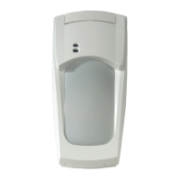
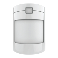
Introduction to the VE735 and VE736 PIR motion sensors with patented verified PIR technology.
Guidelines to avoid potential causes of instability like sunlight, heat, draughts, animals, and obstructions.
Steps for mounting the detector, including lifting the cover, removing the interior, and fixing the base to the wall.
Details on J1 PIR sensitivity, J2 CLM, and J3 Dual loop settings and their functions.
Explains CLM feature for identifying curtain edges and its use for long-range alignment.
Describes the J3 dual loop setting for connecting the detector to any control panel.
Explanation of DIP switch functions for polarity, chime, chime direction, and LEDs.
Procedure for aligning the detector using the VE710 laser alignment tool.
Method for aligning the detector using blinders and walk testing without a laser tool.
Table detailing detector status indication through yellow and red LEDs.
How to remotely enable/disable the walk test LED and control it via DIP switch.
Explanation of alarm memory and how to reset LED indications after an alarm.
How to change coverage patterns using mirror stickers for specific requirements.
Instructions on how to remove and use mirror blinders to block detection curtains.
Description of pry-off and cover tamper features, including compliance and installation notes.
Information on the SB01 swivel-mount bracket for ceiling mounting.
Definitions of key terms used in the installation sheet.
Detailed specifications of the detector's electrical, environmental, and physical characteristics.
| Series | VE700 |
|---|---|
| Manufacturer | Interlogix |
| Category | Accessories |
| Operating Voltage | 12V DC |
| Tamper Output | Normally Closed |
| Storage Temperature | -20°C to +70°C |