EasyManua.ls Logo

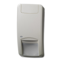
Interlogix DD105 User Manual

Interlogix DD105
24 pages
To Next Page IconTo Next Page
Page #1 background imageLoading...
Page #1 background image
© 2019 UTC Fire & Security Americas Corporation, Inc. 1 / 24 P/N 145919999-4 (ML) • REV K • ISS 14JUN19
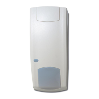
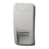
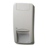
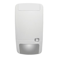
DD100 Series Dual Technology Detector
Installation Sheet
EN
DA
DE
ES
FR
IT
NL
NO
PL
PT
SV
1
2
3
DD100PI DD105/DD105C
4
5
6
BA C
1 2 3 4 5 6 7
5
5 cm
J2
J3
J4
J1
1
2
-0V
+12V
1 2 3 4 5 6 7 8
LED
SPARE
LED
33R
SPARE
LED
SPARE
SPARE
-0V
+12V
1 2 3 4 5 6 7 8
LED
33R
4K7
4K7
Panel
Dual loop zone
Panel
Dual loop zone
J1
J1J1 J1
4K7
4K74K7 4K7
4K7
4K74K7 4K7
33R
33R33R 33R
4
44 4
4
44 4
7
77 7
5
55 5
6
66 6
3
33 3
DD105 Series #1 DD105 Series #2
DD105 Series
DD105 Series # X
PCB PCB
PCB
PCB
1 2
1
Question and Answer IconNeed help?

Do you have a question about the Interlogix DD105 and is the answer not in the manual?

Interlogix DD105 Specifications

General IconGeneral
ColorWhite
Relative Humidity95% max., noncondensing
MaterialPlastic
Power Supply9 to 16 VDC
Operating Voltage9 to 16 VDC

Summary

Detector Installation

Placing the detector

Guidance on optimal detector placement to maximize PIR detection and avoid false alarms.

Mounting instructions

Step-by-step guide for mounting the detector, including preparation and fixing.

Detector Features

Pet immunity (DD100PI only)

Details on pet immunity features for the DD100PI model and installation adjustments.

Window mask

Information on the window mask and its purpose in preventing false alarms.

Jumpers Configuration

J1: Dual loop feature (DD105 and DD105C only)

Explanation of the dual loop feature and its connection via jumper J1.

J2: LED function

Description of LED functions and how to control them via jumper J2.

J3 and J4: Range adjustment

Guidance on adjusting PIR and microwave ranges using jumpers J3 and J4.

Technical Specifications

Related product manuals