EasyManua.ls Logo

Interlogix DDV1016AM User Manual

Interlogix DDV1016AM
52 pages
To Next Page IconTo Next Page
Page #1 background imageLoading...
Page #1 background image
© 2019 UTC Fire & Security Americas Corporation, Inc. 1 / 52 P/N 146667999-1 (ML) • REV G • ISS 19AUG19
DDV1016AM(-D)(-B) Dual Detector Installation
Sheet
EN
DA
DE
ES
FR
IT
NL
PL
PT
SV
1
4
2
3
Note for INCERT installations: Outer curtain sets (1 and 9)
have 12 m range. Detector mounting height must be 2 to 3 m.
B
A
C
A
C
B
A
B
C
B/C
SB01 (1)
Cover screw (2)
ST400 3()
Spare
(1)
(2)
()3
(3)
()4
16 m range (52 ft. 6 in.)
0 m
2 m (6 ft. 6 in.)
4 m (13 ft. 1 in.)
6 m (19 ft. 8 in.)
8 m (26 ft. 2 in.)
2 m (6 ft. 6 in.)
4 m (13 ft. 1 in.)
6 m (19 ft. 8 in.)
8 m (26 ft. 2 in.)
10 m (32 ft. 9 in.)
10 m (32 ft. 9 in.)
12 m (39 ft. 4 in.)
12 m (39 ft. 4 in.)
3.67 (12 ft.) m
16 (52 ft. 6 in.).0 m
2.4 m (7 ft. 10 in.)
(optimum)
Question and Answer IconNeed help?

Do you have a question about the Interlogix DDV1016AM and is the answer not in the manual?

Interlogix DDV1016AM Specifications

General IconGeneral
BrandInterlogix
ModelDDV1016AM
CategorySecurity Sensors
LanguageEnglish

Summary

Installation Overview

Mounting and Placement

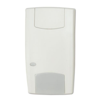
Guidelines for physically mounting the detector, including height recommendations.

Detection Pattern and Range

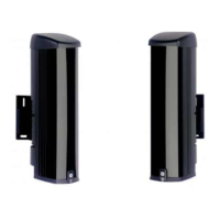
Visual representation of the detector's coverage area and detection range.

Detector Components and Diagrams

Wiring and Terminal Identification

Shows detector terminals and their wiring functions for connections.

Coverage Pattern Options

Illustrates different detection coverage patterns selectable for the detector.

Installation Guidelines and Initial Setup

General Installation Recommendations

Advice on choosing the best location and mounting height for the detector.

DIP Switch Configuration (SW1 & SW2)

Initial configuration of detector settings using DIP switches.

Connections and Detector Settings

Detector Terminal Connections

Detailed mapping of terminals to their functions and power supply.

Jumper Settings for EOL

How to use jumpers to set onboard EOL resistor values for zone configuration.

Advanced Configuration Options

EOL Resistor Configuration

Specific jumper settings for alarm, tamper, and fault EOL resistors.

SW1 General Settings

Configuration of radar range, polarity, and auto remote test via SW1.

Operational Modes and Testing

Remote Functionality and LED Control

How remote settings and LEDs are controlled via DIP switches.

AM Settings and Calibration

Configuration and calibration procedures for AM detection.

Walk Testing Procedure

Methods to perform walk testing to verify detector operation.

Product Information and Compliance

Operational Modes (Green, Alarm Memory)

Explanation of Green mode and how alarm memory functions.

Output Status and Specifications

Details LED status, relay outputs, and technical product specifications.

Regulatory and Manufacturer Information

Includes product warnings, certifications, and manufacturer details.

Related product manuals