4 / 52 P/N 146667999-1 (ML) • REV G • ISS 19AUG19
• Obscuring the detector field of view with large objects,
such as furniture
Microwave hazards:
• Mounting surface susceptible to vibrations
• Metal surfaces reflecting microwave energy
• Water movement through plastic pipes
• Moving or vibrating objects like fans, heating or air-
conditioning ducts
AM hazards:
• Moving objects less then 1 m in front of the detector
• Small insects on the detector
• Modern fluorescent lighting in close proximity (within
1.5 m)
WARNING! The equipment is not earthed. Any
external circuit connected to the equipment must be
located within the same building and connected to a
protective earthing conductor.
Wire insulation of cables connected to the equipment must
conform to IEC 60332-1-2 and IEC 60332-1-3 or IEC 60332-
2-2, depending on the wire cross sectional area, or IEC TS
60695-11-21, regardless of cross sectional area. Alternatively,
such wires must comply with UL 2556 VW-1.
The detector power supply source must be power limited at
15 W.
We recommend that the detector is regularly walk tested and
checked at the control panel.
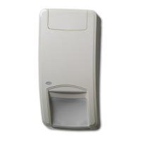
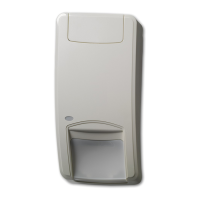
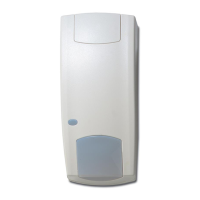
To install the detector:
1. Lift off the custom insert (see Figure 2, items 1 and 2).
2. Using a screwdriver, carefully prise open the detector (see
Figure 2, items 3 and 4).
Caution: Do not touch the pyroelectric sensor (Figure 6).
3. Take out the cover screw (Figure 4, item 2).
4. Fix the base to the wall between 2.0 and 3.0 m (6.6 and
9.8 ft.) from the floor.
See Figure 4. In all positions use a minimum of two M4
screws from the standards DIN 7505B, DIN 96, DIN 7996,
or a screw with a head with 8 mm diameter and a flat
surface.
- For flat mounting, use screws in positions A.
- For corner mounting, use screws in position B or C.
Note: For EN 50131 Grade 3 installations, do not use
mounting position C.
- To install the pry-off tamper ST400, use mounting
positions A. ST400 mounting position is shown as item 3
in Figure 4. Open the outlet in the back plate (Figure 5,
item 2).
5. Wire the detector (see Figures 4 and 12). Use back plate
cable inlets (Figure 5, item 1) and cable gutter (Figure 5,
item 3).
6. Select the desired jumper and DIP switch settings (see
“Setting the detector” below for more information.
7. Remove the blinders and add the stickers, if required. See
“Configuring the coverage pattern” on page 6 for more
details.
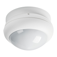
8. For ceiling-mount applications, use the SB01 swivel-mount
bracket. SB01 mounting position is shown as item 1 in
Figure 4.
9. Close the cover, insert the cover screw, and place the
custom insert.
Connections
See Figure 12.
Table 1: Detector Connections
Power supply connection (9 to 15 V, 12 V
nominal)
Alarm relay output (33 Ω). Use jumper JA to
set the onboard EOL resistor in series with the
relay. See “Jumpers” below.
Tamper switch output (0 Ω). Use jumper JT to
set the onboard EOL resistor in series with the
switch. See “Jumpers” below.
This input enables and disables the LED (walk
test On/Off). Walk test mode can only be
entered when detector is in Day mode (pin 8).
Active high or low is determined by SW1-3
(see “SW1-3: Polarity” on page 5).
This input switches the detector in day (show
memory on the LED indicator) or night mode
(activates the alarm memory and clears
previous stored alarms). Active high or low
polarity is determined by SW1-3 (see “SW1-3:
Polarity” on page 5).
Fault Relay output (33 Ω). Use jumper JF to
insert one of the on-board EOL resistors in
series with the relay. See “Jumpers” below for
the correct resistor settings.
Notes
• Inputs 7 and 8 are only useable when SW1-5 is set to
Remote on. See “SW1-5: Remote functionality” on page 6.
• The LED is only enabled when SW1-6 is set to LED on.
Figure 10 explains how to create a single zone with multiple
resistor configuration.
Figure 10
(1) Alarm relay
(2) Alarm zone
(3) Tamper switch output
(4) Fault relay
Ra Alarm EOL resistor
Rt Tamper EOL resistor
Rf Fault EOL resistor
Setting the detector
See Figure 13 for jumpers and DIP switch location.
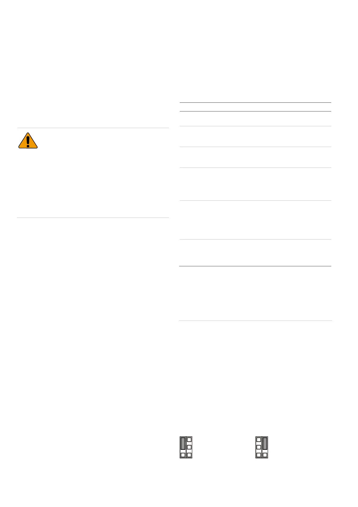
Jumpers
Jumpers set onboard EOL mode and value. The circuit is
shown in Figure 10.
JA: Set onboard alarm EOL resistor (Ra)