P/N 146667999-1 (ML) • REV G • ISS 19AUG19 5 / 52
Off: No onboard alarm EOL.
JT: Set onboard tamper EOL resistor (Rt)
Off: No onboard tamper EOL.
JF: Set onboard fault EOL resistor (Rf)
Off: No onboard fault EOL (factory default).
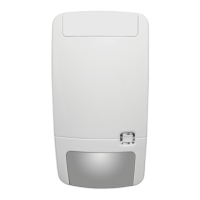
J1: Set zone EOL mode
On: 3-resistor single zone.
Off: Isolated fault contact and 2-resistor zone.
Configuring the zone
To set up the zone, apply the following guidelines.
• Select appropriate EOL resistor values with JA, JT and JF.
For example, setting of jumper JT determines Rt value.
• For isolated outputs remove JT and J1.
• Remove jumpers JA, JT and JF to exclude onboard EOL
values.
• For dual resistor setting remove J1 and use terminal 3
and 6.
For a single zone with all onboard resistors set, the zone
resistance can be the following.
Table 2: Zone resistance values
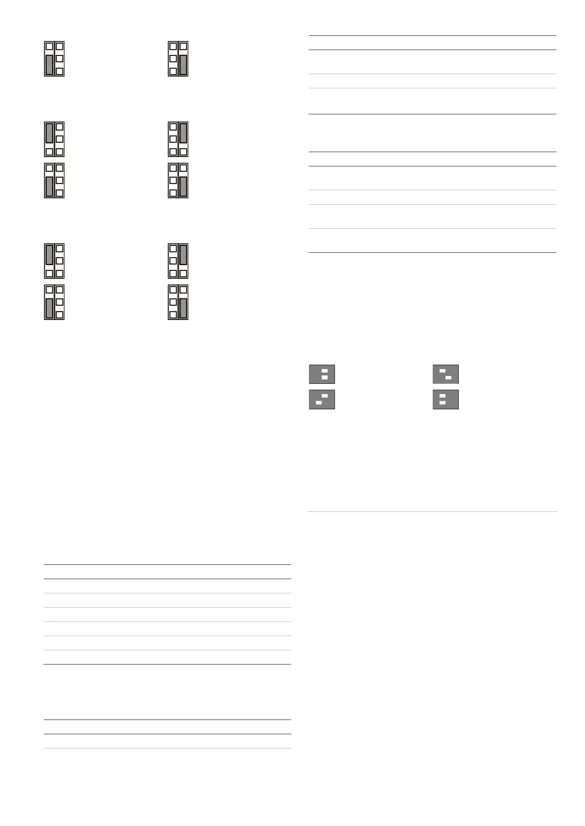
DIP switches
Table 3: SW1, general settings
On: Auto remote test
enabled
Off: Auto remote test
disabled*
1 On, 2 On: 16 m (52 ft.)*
1 Off, 2 On: 14 m (46 ft.)
1 On, 2 Off: 12 m (39 ft.)
1 Off, 2 Off: 10 m (33 ft.)
* Factory default
Table 4: SW2, AM settings
On: AM to fault and
alarm relays*
Off: AM to fault relay
only
On: Advanced AM
sensitivity*
Off: Standard AM
sensitivity
* Factory default
DIP switch SW1, general settings
SW1-1, SW1-2: Radar range
Use SW1-1 and SW1-2 to set the radar range exactly to fit the
application. The radar is of a range-gating type which means
that the range of detection is very accurate.
16 m (52 ft.)
Factory default.
SW1-3: Polarity
On: Positive polarity. Configures the inputs (WT and D/N) as
“Active high”.
Off: Negative polarity. Configures the inputs (WT and D/N) as
“Active low”. Factory default.
The functionality is explained in Figure 9.
Figure 9
(1) Polarity high
(2) Polarity low
(3) Walk test
(4) Day/night
This function also depends on the SW1-5 setting. See “SW1-5:
Remote functionality” on page 6.
SW1-4: Auto remote test
On: Auto remote test on. Enables Auto remote test.
Off: Auto remote test off. Disables Auto remote test (factory
default).
If auto remote test is enabled, the control panel can trigger the
detector to perform a diagnostic test. This test is activated by
switching to walk test mode (day mode and WT enabled). The
detector activates the alarm relay if the test result is positive,
and the fault relay if the test result is negative. After the test the
detector continues with normal operation.
This function also depends on the SW1-5 setting. See “SW1-5:
Remote functionality” on page 6.