P/N 146576999-1 (ML) • REV D • ISS 08MAR19 3 / 10
EN: Installation Sheet
Introduction
The EV1100-D series includes the EV1116-D and EV1116AM-
D PIR motion sensors. They have a patented mirror, pyro and
signal processing technology.
Installation guidelines
The technology used in these detectors resists false alarm
hazards. However, avoid potential causes of instability (see
Figure 1) such as:
• Direct sunlight on the detector
• Strong draughts onto the detector
• Heat sources within the detector field of view
• Animals within the detector field of view
• Obscuring the detector field of view with large objects,
such as furniture
• Objects within 50 cm of the anti-masking (AM) detector
• Installing two detectors facing each other and less than
50 cm apart (only AM detectors)
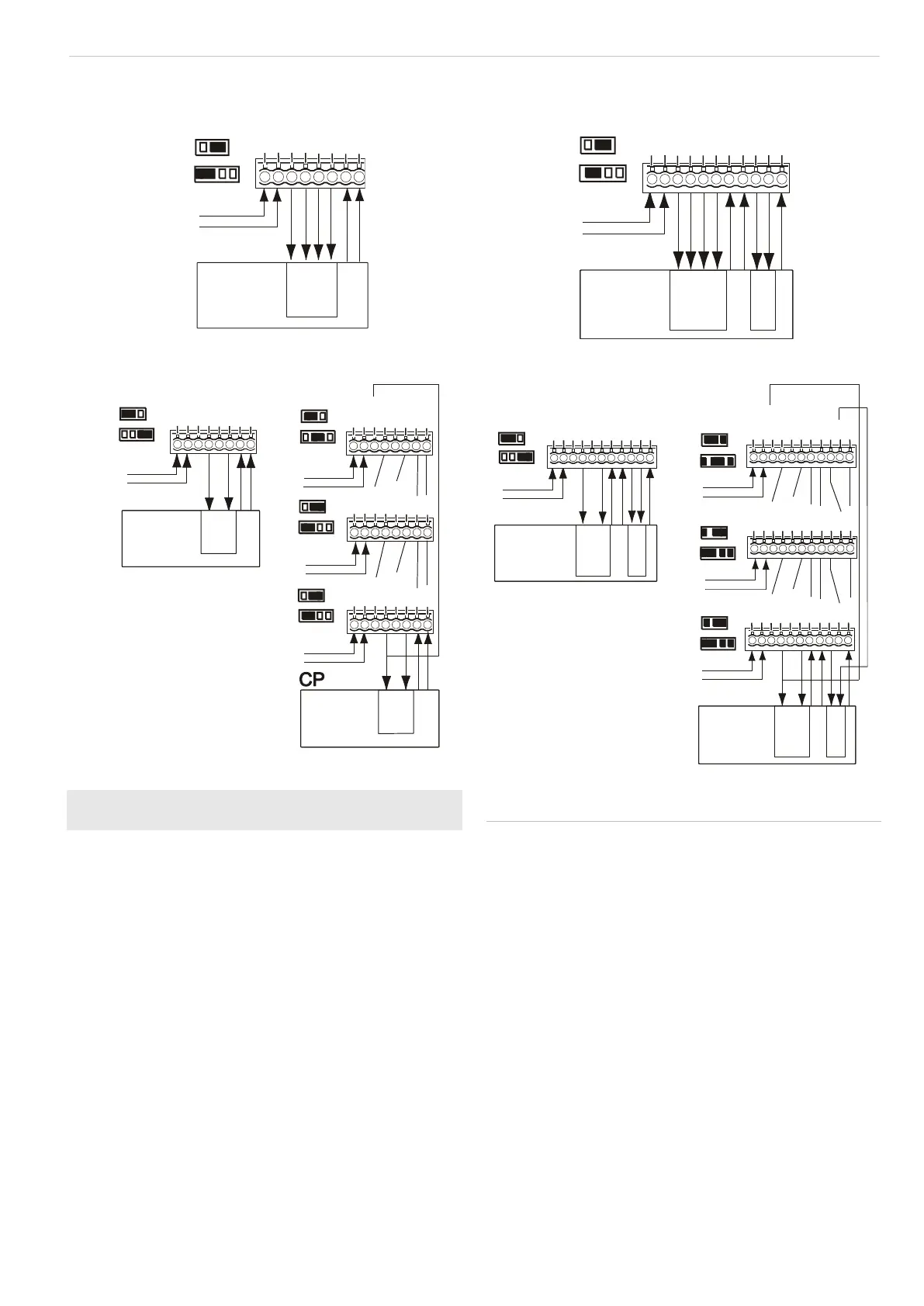
Installing the detector
Figure 7
(1) Single core connection
(2) Standard connection (factory
default)
(3) Dual loop connection
CP Control panel
WT Walk test
AM Antimasking
D/N Day/night
Rtest Remote test
To install the detector:
1. Lift off the custom insert and remove the screw
(see Figure 2, step 1).
2. Using a screwdriver, carefully prise open the detector (see
Figure 2, steps 2 and 3).
3. Fix the base to the wall between 1.8 and 3.0 m from the
floor. For flat mounting use a minimum of two screws (DIN
7998) in positions A. For corner-mounting use screws in
positions B or C (Figure 3). To install a pry-off tamper, use
position A or C.
4. Wire the detector (see Figures 3 and 7).
Zone X
1
2
3
4
5
6
7
GND
+12V
Alarm
Alarm
Tamper
WT
Tamper
J3
J4
8
D/N
CP
Normal
larmA
< 33 Ω
8
Zone Y
+12V
Tamper
WT
Tamper
1
2
3
4
5
6
7
8
9
10
GND
Alarm
D/N
AM
AM
Alarm
Zone X
J3
J4
11
Rtest
CP
Normal
larmA
< 33 Ω
8
Zone X
1
2
3
4
5
6
7
GND
+12V
Alarm
Alarm
Tamper
WT
Tamper
J3
J4
Zone X
GND
+12V
Alarm
Alarm
Tamper
WT
Tamper
GND
+12V
Alarm
Alarm
Tamper
WT
Tamper
GND
+12V
Alarm
Alarm
Tamper
WT
Tamper
J3
J3
J4
J3
J4
8
D/N
1
2
3
4
5
6
7
8
1
2
3
4
5
6
7
8
1
2
3
4
5
6
7
8
D/N
D/N
D/N
J4
CP
Normal
larmA
Tamper
Short
4.7 k
9.4
0
Ω
kΩ
Ω
8
Normal
larmA
Tamper
Short
4.7 k
9.4
0
Ω
kΩ
Ω
8
Zone Y
+12V
Tamper
WT
Tamper
1
2
3
4
5
6
7
8
9
10
GND
Alarm
D/N
AM
AM
Alarm
Zone X
J3
J4
Zone Y
+12V
Tamper
WT
Tamper
GND
Alarm
D/N
AM
AM
Alarm
Zone X
+12V
Tamper
WT
Tamper
GND
Alarm
D/N
AM
AM
Alarm
J3
J4
J3
J4
J3
J4
11
Rtest
1
2
3
4
5
6
7
8
9
10
11
1
2
3
4
5
6
7
8
9
10
11
1
2
3
4
5
6
7
8
9
10
11
Rtest
Rtest
CP
CP
+12V
Tamper
WT
Tamper
GND
Alarm
D/N
AM
AM
Alarm
Rtest
Normal
larmA
Tamper
Short
AM/TF
4.7 k
9.4
0
Ω
kΩ
Ω
88
Normal
larmA
Tamper
Short
AM/TF
4.7 k
9.4
0
Ω
kΩ
Ω
88