4 TruPortal Dual Door Interface Module Quick Reference
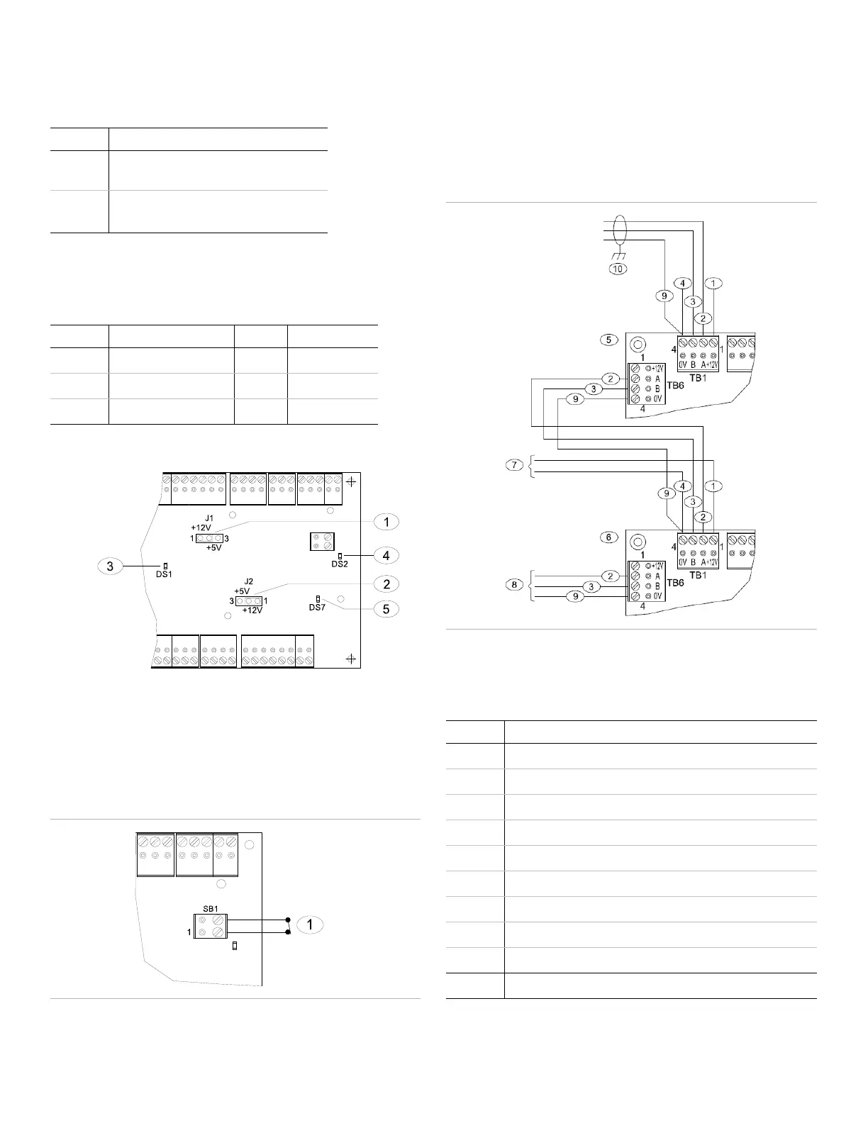
Reader Voltage Jumpers
For reader power (data line pull-up) voltage selection, refer to the
following table and Figure 6:
Reader Status LEDs
To interpret reader status LEDs, refer to the following table and
Figure 6:
Figure 6: Reader Jumpers and LEDs
Alarm Input Door Contact Detail and Request to Exit
Note the following details about the Figure 7:
• Door contacts (NC & NO) are for reference only, and must
match the door state.
• Callout #1 represents the enclosure tamper switch.
Figure 7: Tamper Wiring
Communications (SNAPP Bus) and Power Wiring
Communication ports TB1 and TB6 are two-wire RS-485
interfaces used to connect RS-485 from the System Controller
(TP-SYS) to additional input/output (I/O) modules downstream.
The interface allows multidrop communication on a single bus of
up to 4000 feet (1200 m). Use twisted pairs (minimum 22 AWG /
0.644 mm / 0.326 mm) with an overall shield for communication.
Figure 8: Communications Power Wiring
Note: Door Interface Modules (TP-ADD boards) cannot be
powered from the System Controller (TP-SYS).
Callout Description
1 Use J1 pins 1 and 2 for +12 VDC Data Lines.
Use J1 pins 2 and 3 for +5 VDC Data Lines
2 Use J2 pins 1 and 2 for +12 VDC Data Lines;
Use J1 pins 2 and 3 for +5 VDC Data Lines
Callout Indication LED State
3 485-SNAPP bus OK DS1 ON Green
4 Processor OK DS2 Flashing Green
5 Low power DS7 ON Red
Callout Description
1 +12 V from TP-ADD power supply, pre-wired at the factory
2 Data A from System Controller (TP-SYS)
3 Data B from System Controller (TP-SYS)
4 0 V from TP-ADD power supply
5 TP-ADD-2D-BRD
6 TP-ADD-2D-BRD (downstream)
7 +12 V and 0 V external power source, pre-wired at the factory
8 To additional TP-ADD-2D or TP-ADD-IN/OUT boards
9 Common ground from System Controller (TP-SYS)
10 Terminate cable shield to ground lug in System Controller

 Loading...