TruPortal Dual Door Interface Module Quick Reference 3
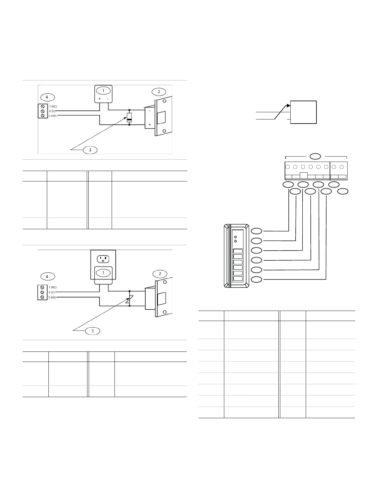
Output Wiring
The contact protection circuit must be used. The two circuits
shown in Figure 2 and Figure 3 are recommended. Locate the
protection circuit as close to the load as possible (within 12 in.
[30 cm]), as the effectiveness of the circuit will decrease if it is
located further away.
Figure 2: Recommended Circuit #1
Figure 3: Recommended Circuit #2
Magnetic Locks and Other “Fail-Safe” Door Locks
The default door lock wiring is for “Fail Secure” (powered =
unlocked). For magnetic locks and other “Fail-Safe” door locks
(powered = locked), move the Normally Open (NO) wire to
Normally Closed (NC) terminal for the specific unlock relay.
Note: The System shall not be installed in the Fail Secure
mode unless permitted by the local authority having
jurisdiction and shall not interfere with the operation of
panic hardware. (Not evaluated by UL.)
Figure 4: Door Lock Wiring
Reader Wiring
Figure 5: Reader Wiring
The following table lists the items shown in Figure 5
For the second reader of each door, the reader connections are
shared (except for the Data 0 and Data 1, which are separate for
each reader).
Callout Description Callout Description
1 12 VDC 3 Diode current rating >1x strike
current. Diode breakdown voltage
>4x strike voltage for 12 or
24 VDC strike. Diode 1N4002
(100 V/1 A) typical.
2 DC strike 4 TB5 or TB8 on module.
Callout Description Callout Description
1 AC transformer 3 Clamp voltage >1.5x VAC RMS.
For 24 VAC strike, Panasonic
ERZ-CO7DK470 is typical.
2 AC strike 4 TB5 or TB8 on module.
Callout Description Callout Description
1 Reader (TB2 or TB11
on module)
9R2 Data 0
2 (+) 5/12 VDC 10 Red (1)
3 Green LED 11 Brown (4)
4 Red LED 12 Orange (5)
5 R1 Data 1 13 White (3)
6R1 Data 0 14Green (2)
7 (-) 0V Signal Ground 15 Black (6)
8R2 Data 1
123456 12
TB11
5/12 GRN
RED/
RXD GNDR1D1 R1D0 R2D1 R2D0
01
23
45
67
89
*
#
5
4
1
3
2
10
9
6 8
7
15
14
13
12
11

 Loading...