2 TruPortal Dual Door Interface Module Quick Reference
Mounting the Enclosure
1. Remove enclosure from shipping container and remove any
packing material.
2. Using the template provided (part number 531119001 or
531120001), mark and then drill mounting holes.
3. To mount on dry wall, use 1/8 in. (3.175 mm) hollow wall,
expansion anchors. Unscrew the screws from the anchors.
Mark the mounting holes. Force a starter hole in each mark
with a sharp tool. Hammer the anchors into each hole. Align
the box mounting holes over the anchor holes and screw in
the anchors until tight.
To mount on a concrete surface, hold the enclosure on the
mounting surface. Mark the mounting holes. Use a hammer
drill with a 3/16 in. (4.76 mm) carb alloy drill bit and make
1 in. (25.4 mm) deep holes in each marking. Insert a # 6-8
plastic anchor in each hole and hammer them in. Use # 8 X
1 in.(25.4 mm), Phillips wood screws to screw into the plastic
anchors and mount the enclosure.
4. The enclosure includes standard cable knockouts on each
side, including the back. Use the proper size and type of
cable strain reliefs to secure cables to the enclosure.
See Figure 10 for TP-ADD-2D enclosure dimensions. For
TP-ADD-4D dimensions, see Figure 11.
Mounting the Module in the Enclosure
Use the provided hardware as required to mount the module in
the enclosure.
Note: Do not over-tighten the mounting screws.
• To mount the module in the AL400 enclosure using the
mounting plate, see Figure 12.
• To mount the module in the AL600 enclosure using the
mounting plate, see Figure 13.
• To mount the module in AL400 enclosure without the
mounting plate, see Figure 14.
• To mount the module in AL600 enclosure without the
mounting plate, see Figure 15.
Wiring
(See Figure 1.)
For the Door Unlock Circuit, a diode is provided to protect against
voltages induced when a DC strike is de-energized. For an AC
strike, or a magnetic-lock with reversing coils (or if unsure), a 27 V
Metal Oxide Varistor (MOV) must be used.
Verify that at least 10.5 VDC is at each device (with relays
energized). Use additional power supplies as necessary.
For large current-draw devices with built-in power supplies,
connect the incoming and outgoing module bus +12 VDC lines
together, but do not connect to the +12 VDC in the enclosure.
Terminal Block (TB) 6 can be used to daisy chain the SNAPP bus.
Bring the bus wiring through TB1 and continue the wiring out
through TB6.
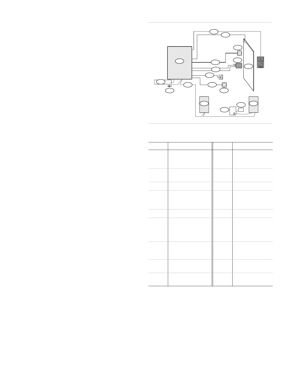
Figure 1: Components and Cable Specifications
The following table lists the items shown in Figure 1.
Callout Description Callout Description
1 Reader cable (22 AWG,
(0.64 mm / 0.33 mm
2
)
shielded, 3 pairs)
10 Door 1 or 2 (with door
closer)
2 Door contact/sensor
wiring (22 AWG, 1 pair)
11 Last module
3 Request to Exit (RTE) 12 Transformer
4 RTE button wiring
(22 AWG (1.02 mm/
.82 mm
2
), 1 pair)
13 Power supply
5 Door lock 14 Next module
6 Door lock wiring
(18 AWG, 1 pair)
15 Module bus (24 AWG
(.51 mm/.20 mm
2
),
four shielded wires,
120 ohms)
7 AUX relay wiring
(22 AWG, 1 pair)
16 To System Controller
(TP-SYS) or previous
module
8 AUX input wiring
(22 AWG, 1 pair)
17 12 VDC input power
9 AUX input 18 Dual Door Interface
Module (TP-ADD)
*
5
4
1
3
2
10
9
6
8
7
15
14
13
12
11
18
17
16
 Loading...