EasyManua.ls Logo

Intermatic IDIGITAL DT104 User Manual

Intermatic IDIGITAL DT104
12 pages
To Next Page IconTo Next Page
Page #1 background imageLoading...
Page #1 background image
7777 Winn Road
Spring Grove, Illinois 60081
www.intermatic.com
IDIGITAL — 24-Hour Digital Time Switch
MODEL DT104
Clear Mem
Clear Entry
BATTERY
MODE
RESET
ENTER
NEXT
+
ON/
OFF
ON/
OFF
-
DT104
SAFETY SECTION
WARNING
Risk of Fire or Electrical Shock
Disconnect power at the circuit breaker(s) or disconnect switch(es) before installing or servicing.
Installation and/or wiring must be in accordance with national and local electrical code requirements.
This enclosure does not provide grounding between conduit connections. When metallic conduit is used, you must also install grounding type bushings and jumper wire.
Use #14-#12 AWG wires, rated at least 75°C (167°F)-COPPER conductors ONLY.
If the power disconnect point is out of sight, lock it in the OFF position and tag it to prevent unexpected application power.
Make sure there is no wire insulation under the terminal plate on the time switch connector. Firmly tighten terminal screws.
Do not remove insulator that is covering terminals.
KEEP DOOR CLOSED AT ALL TIMES when not servicing.
NOTICE
Do NOT touch circuit board components. Contact can create a static discharge, which can damage the microprocessor.
PRODUCT DESCRIPTION
The Intermatic DT104 Digital 24-Hour Time Switch automatically switches loads to a preset daily schedule with to-the-minute
accuracy. Use the DT104 as an ON/OFF timer in applications requiring 24-hour load control such as lighting, air conditioning
systems, pumps, etc. Each load output of the Time Switch can support up to 14 timed ON and 14 timed OFF events per day.
The program can be overridden by pushing the ON/OFF load override button(s). The DT104 Time Switch is designed to directly
switch tungsten or ballast loads up to its rating, and inductive or resistive loads up to 20 A at 120, 208, 240 or 277 VAC.
Specications
Time Switch
Input Voltage: 120–277 VAC, 60 Hz
Power Consumption: 6.0 W Max.
Contact Configuration: 2xSPST or 1xDPST
Switch Ratings
20 A Inductive/Resistive, 120/240 VAC
20 A Magnetic Ballast, 120-277 VAC
1 A Electronic Ballast, 120-277 VAC
20 A Resistive, 28 VDC
5 A Tungsten: 120/240 VAC
1 HP, 120 VAC
2 HP, 240 VAC
Set Points (Events)
The load output of the Time Switch can support up to
14 timed ON and 14 timed OFF events per day.
Battery-Powered Clock Operation
3 year minimum (uses two AAA industrial-grade
alkaline nonrechargeable 1.5 V batteries, supplied)
Minimum ON or OFF time
1 minute
Maximum ON or OFF time
23 hours, 59 minutes
Shipping Weight
2.5 lb. (1.1 kg)
Enclosures
TYPE 1 indoor metal enclosure
Knockouts
Combination 1/2-3/4" size (one on back, one on each
side, two on bottom)
Wire Size
#14-#12 AWG
Question and Answer IconNeed help?

Do you have a question about the Intermatic IDIGITAL DT104 and is the answer not in the manual?

Intermatic IDIGITAL DT104 Specifications

General IconGeneral
ProgrammableYes
DisplayLCD
Shortest ON/OFF Time1 minute
TypeDigital Timer
Amperage15A
MountingWall
Number of Programs7

Summary

Safety Section

Risk of Fire or Electrical Shock Warnings

Essential safety precautions and warnings regarding electrical hazards during installation and use.

Notice Regarding Circuit Board Handling

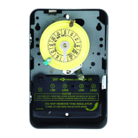
Cautionary note about avoiding static discharge when touching internal components.

Product Description

Specifications

Time Switch Specifications

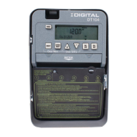
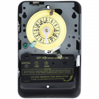
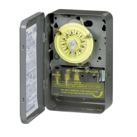
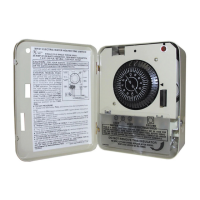
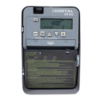
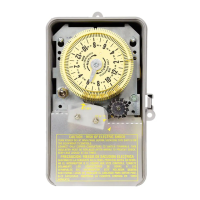
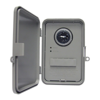
Details on input voltage, power consumption, and contact configuration of the time switch.

Switch Ratings

Lists the maximum load ratings for various types of electrical loads.

Battery-Powered Clock Operation

Information regarding the battery life and type used for clock operation.

Shipping and Enclosure Details

Provides shipping weight, enclosure type, knockout sizes, and wire size recommendations.

Installation Guide

Preparing the Time Switch

Steps to prepare the timer, including setting voltage, DST, and load control mode.

Mounting the Time Switch Enclosure

Instructions for securely mounting the unit's enclosure in the desired location.

Connecting the Wires

Detailed guide on stripping wires, connecting them to terminals, and grounding.

Initial Setup and Powering

Powering the Time Switch

Instructions for installing batteries and applying power to the time switch.

Setting the Date

Procedure for accurately setting the current date on the time switch.

Setting the Time

Procedure for accurately setting the current time on the time switch.

Programming and Operation

Setting On/Off Events

Guide to programming timed ON and OFF events for load control.

Deleting (Clearing) an Event

Optional steps to remove or cancel a programmed event.

Operating the Time Switch Modes

Instructions for selecting AUTO or MANUAL operating modes.

Editing Programmed Events

How to review and modify existing programmed ON/OFF events.
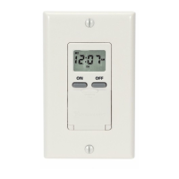
Related product manuals