3
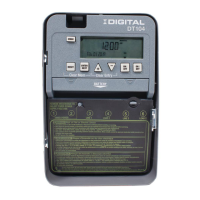
IDIGITAL — 24-Hour Digital Time Switch
L2/N
Line 1
123456
Timer Power
ON OFF
Install jumper only if timer input
and load voltage are the same
120/208/240/277 VAC Input
L2/N
Line 1
Timer Power
Load
1
Load
2
120/208/240/277 VAC Input
L2/N
Line 1
123456
Timer Power
Load
1
Load
2
120/208/240/277 VAC Input
Line 2
Line 2
Line 1
Line 1
123456
Timer Power
Load
Install jumper only if timer input
and load voltage are the same
240 VAC Input
Line
1
Line
2
Line
1
Line
2
DT104 configured for 2 SPST
loads with jumper set to IND
L2/N
Line 1
123456
Timer Power
ON OFF
Install jumper only if timer input
and load voltage are the same
120/208/240/277 VAC Input
L2/N
Line 1
123456
Timer Power
Load
1
Load
2
120/208/240/277 VAC Input
L2/N
Line 1
123456
Timer Power
Load
1
Load
2
120/208/240/277 VAC Input
Line 2
Line 2
Line 1
Line 1
Timer Power
Load
Install jumper only if timer input
and load voltage are the same
240 VAC Input
FIG. 5c DT104 configured for 240VAC DPST
load with jumper set to SIM
L2/N
Line 1
123456
Timer Power
ON OFF
Install jumper only if timer input
and load voltage are the same
120/208/240/277 VAC Input
L2/N
Line 1
123456
Timer Power
Load
1
Load
2
120/208/240/277 VAC Input
L2/N
Line 1
Timer Power
Load
1
Load
2
120/208/240/277 VAC Input
Line 2
Line 2
Line 1
Line 1
123456
Timer Power
Load
Install jumper only if timer input
and load voltage are the same
240 VAC Input
Line
1
Line
2
FIG. 5d DT104 configured for DPST loads with
jumper set to SIM
Powering the Time Switch
1. Remove the battery case by sliding it down as shown
by the arrows, then install two AAA alkaline batteries.
Make sure the batteries are pointing in the direction
shown in FIG.6.
Note: Replace batteries every 2-3 years with two AAA
industrial-grade alkaline nonrechargeable 1.5 V
batteries. You do not need to remove the Time
Switch or field wiring in order to replace the
batteries.
2. Verify that the display is ON to make sure the batteries
are OK. If the display shows scrambled information,
press the RESET button to clear it up.
3. Apply power to the Time Switch.
Proceed to the Initial Setup section.
Note: You must reset the Time Switch using this procedure
whenever you change the jumpers described in
FIG.2 (SIM/IND/PUL or DST). To reset the Time
Switch, press and hold the ENTER button, then
press the RESET button. The screen will flash 12:00
AM, and the Time Switch status is Manual Mode.
Clear Mem Clear Entry
BATTERY
MODE
RESET
+
–
ENTER
NEXT
ON /
OFF
ON /
OFF
1.5 V
AAA BATTERY
1.5 V
AAA BATTERY
Battery Cover
FIG.6 Inserting the Batteries
INITIAL SETUP
Overview
Upon first use, you must set the Date and Time before you can program any other settings.
If you make a mistake during any of the programming steps,
press the MODE button to cycle through the Time Switch
menus until you locate the error and then correct the entry.
Setting the Date
1. Press the MODE button repeatedly until the words
SET and DATE appear in the upper area of the display.
SeeFIG.7.
2. Press the + or – buttons to enter the current Month.
3. Press the ENTER/NEXT button to save the month.
4. Repeat steps 2 and 3 to set the Date and Year.
5. Press the MODE button to exit and advance to the
Setting the Time section.
Setting the Time
1. If necessary, press the MODE button repeatedly until
the words SET and CLOCK appear in the upper area of
the display. See FIG.8.
2. Press the + or – buttons to enter the current time.
Note: To go from AM to PM, keep pressing the + or – buttons
to cycle through the day. You can hold the + or – buttons
down for 3 seconds to make the time scroll quickly.
3. Press the MODE button to finish and proceed to the
Programming section.
MODE
RESET
+
–
ENTER
NEXT
ON /
OFF
ON /
OFF
SET DATE
Month
Date
Year
FIG.7 Setting the Date
MODE
RESET
+
–
ENTER
NEXT
ON /
OFF
ON /
OFF
SET
AM
PM
CLOCK
Time
FIG.8 Setting the Time
 Loading...