EasyManua.ls Logo

Intermatic PB314EK - User Manual

Intermatic PB314EK
2 pages
Print Icon
To Next Page IconTo Next Page
Loading...
PB300E SERIES
TIME CONTROLS
INSTALLATION
OPERATION &
SERVICE MANUAL
24 Hr. Electronic Timer Replacement/Upgrade Kits
Model: PB313EK; Clock Supply Voltage: 120 V. 50-60 HZ
Model: PB314EK; Clock Supply Voltage: 240 V. 50-60 HZ
GENERAL INFORMATION
SPECIFICATIONS
The PB300EK Series Electronic Timers are made
to fit and replace most PB series Intermatic and
certain other brand mechanical
or electronic timers. The connected load
however, must not exceed the rating of this
timer. The timer is completely enclosed and a
replaceable lithium battery will hold up memory
for up to three years.
The kit contains all the necessary hardware for a
speedy repair or exchange.
Rating:
16A-Resistive, 8A FLA
Contact Configuration:
Single Pole, Double Pole
Power Consumption:
8V A
Battery Type:
CR2032 (1.5V Lithium)
Battery Life:
3 Years Minimum
No. of Programming Periods:
8 On/8 Off
Minimum Interval:
1 minute
INSTALLATION
CAUTION:
• Priortoinstallation,disconnectelectricityatmainpanel
• Makesuretheclocksupplyvoltageofthetimerslatedforreplacementisthesameasthistimer.
• Makesuretheintendedloadiswithinthecapacityofthistimer-seespecificationsabove.
1. Both the old and the new timers have two sets of terminals: LOAD and CLOCK SUPPLY. Identify and mark the
leads connected to these terminals.
2A. OldTimerwithfour1/4inchtabs:Remove female terminals from tabs and remove timer. Install new timer, using
the screws and nuts supplied. Reconnect the two clock supply leads to CLOCK SUPPLY terminals and either one of
the load leads to terminal C and the other load lead to N.O. (normally open) terminal.
2B. OldTimerwithtwoCLOCKSUPPLYLEADSandtwo1/4inchLOADtabs:Disconnect leads at twist on wire
connectors and remove female terminals from tabs. Remove timer. Install new timer, using the screws and nuts sup-
plied. Connect the stripped ends of either leads (supplied) to either wire-nutted junctions. Connect either one of the
load leads to terminal C and the other load lead to N.O. (normally open) terminal.
2C. For other than Intermatic made timers, timers with 5 tabs and/or permanently attached leads, identify first each lead
or tab then follow 2A or 2B above and corresponding markings on back of new timer.
INDEPENDENT
CLOCK SUPPLY
.250 MALE QUICK CONNECT
TERMINALS.
MYLAR INSULATOR
PROTECTING BATTERY
CONTACTS-REMOVE
BEFORE INSTALLATION
NC
NO C
http://waterheatertimer.org/Timer-modules.html#PB
Question and Answer IconNeed help?

Do you have a question about the Intermatic PB314EK and is the answer not in the manual?

Overview

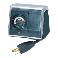
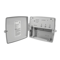
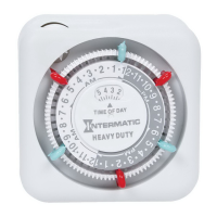
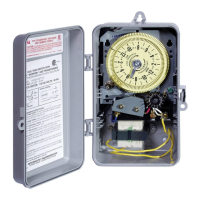
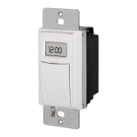
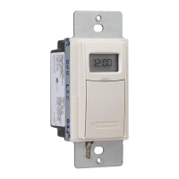
The Intermatic PB300E Series Time Controls are 24-hour electronic timer replacement/upgrade kits designed to fit and replace most PB series Intermatic and other brand mechanical or electronic timers. These kits are suitable for various applications, with two models available: the PB313EK for 120 V. 50-60 Hz clock supply voltage and the PB314EK for 240 V. 50-60 Hz clock supply voltage. The timers are completely enclosed and feature a replaceable lithium battery to retain memory for up to three years. The kit includes all necessary hardware for installation.

Function Description:

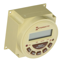
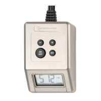
The PB300E Series timers allow users to program up to eight ON/OFF periods per day, providing automated control over connected loads. The timer features a digital display showing the current time and programming status. It includes dedicated buttons for setting the clock, programming ON/OFF times, and overriding automatic operation. An indicator LED illuminates when the timer is connected to a power source and its contacts are closed. The timer can operate in ON, AUTO, or OFF modes, selected via a dedicated button.

Important Technical Specifications:

  • Models: PB313EK (120 V. 50-60 Hz) and PB314EK (240 V. 50-60 Hz)
  • Rating: 16A Resistive, 8A FLA
  • Contact Configuration: Single Pole, Double Pole
  • Power Consumption: 8 VA
  • Battery Type: CR2032 (1.5V Lithium)
  • Battery Life: 3 Years Minimum
  • Number of Programming Periods: 8 On/8 Off
  • Minimum Interval: 1 minute
  • Dimensions: The timer has a front face of approximately 2.362 inches by 2.362 inches, with a depth of about 1.102 inches.
  • Terminals: Features .250 male quick connect terminals for load and clock supply connections. An independent clock supply is indicated.

Usage Features:

  • Setting Time of Day: To set or change the time, users press and hold the CLOCK key while pressing either the HOUR or MINUTE keys until the desired time is displayed. Releasing the CLOCK key sets the time. To clear the entire memory, the reset port can be used.
  • Programming ON/OFF Times: Pressing the TIMER key enters program mode. The display will show "1 ON -- --". Users then press HOUR and MINUTE keys to select the first ON time, followed by another press of the TIMER key to set the first OFF time. This sequence is repeated for up to eight ON/OFF times. After programming, pressing the CLOCK key and then the SELECT key repeatedly until the indicator bar is above "AUTO" returns the timer to automatic operation.
  • Reviewing Program: Pressing the TIMER key repeatedly allows users to review the programmed ON/OFF times. Pressing the CLOCK key returns to the time of day.
  • Canceling/Changing Program: To modify a specific ON or OFF time, press the TIMER key repeatedly until the desired period appears, then set the new time as described above.
  • Overriding Automatic Operation:
    • One-time Override: Pressing the OVR. KEY will temporarily override the current program. The timer will resume automatic operation with the next opposite setpoint.
    • Permanent Override: Pressing the SELECT key moves the indicator bar to the desired ON or OFF position, keeping the timer in that state until the indicator bar is repositioned above "AUTO."
  • Installation: The manual provides detailed instructions for replacing old timers with four 1/4 inch tabs, two clock supply leads and two 1/4 inch load tabs, or other non-Intermatic timers. It emphasizes identifying and marking leads before installation and ensuring the load is within the timer's capacity.

Maintenance Features:

  • Battery Replacement: The timer uses a CR2032 lithium battery, which typically lasts a minimum of three years. A "Blank Display" symptom often indicates a discharged battery, requiring replacement.
  • Troubleshooting: The manual includes a troubleshooting guide for common issues:
    • Blank Display: Possible causes are a discharged battery or a defective timer. Corrective actions are to replace the battery or the timer.
    • Timer Not Responding to Programming: This may occur if the memory is full, requiring a press of the reset port to clear memory.
    • Timer Not Functioning as Programmed: This could be due to the timer being in the wrong SELECT mode, in which case the SELECT key should be pressed to move the indicator bar over to AUTO.
    • Timer is ON at All Times: This indicates the timer is in ON mode or is defective. The corrective action is to adjust the mode or replace the timer.
  • Warranty: Intermatic Incorporated offers a one-year limited warranty, covering defects in material or workmanship. The warranty specifies conditions for repair or replacement and excludes damages from misuse, unauthorized repair, or exceeding product cost. Warranty service is available by returning the product to the dealer or mailing it to an authorized service center.

Intermatic PB314EK Specifications

General IconGeneral
BrandIntermatic
ModelPB314EK
CategoryTimer
LanguageEnglish

Related product manuals