Connect the GREEN wire to the grounding screw in the box. If
a plastic box, connect to ground as supplied.
Make sure all twist connectors are tight.
If a 3-Way Switch Setup:
NOTE: The distance between
switch timer and remote switch
must not exceed 100 feet.
Locate the COMMON
wire connected to first old
switch. It might be attached
to a different colored screw,
or find markings on old switch.
Connect BLACK wire from switch timer to COMMON wire,
using a twist connector.
Connect the other two wires from the old switch to the Blue
and RED wires from the switch timer.
Connect the GREEN wire to the grounding screw in the box. If
a plastic box, connect to ground as supplied.
Using diagram #1 below. Identify and remove wire “C” from
the “Common” terminal of your existing remote switch.
Using diagram # 2 below, remove and reconnect wires “B”
and “C” to the “Common” terminal of your remote switch,
using the supplied piece of jumper wire, if necessary. Follow
diagram # 3 below, if using a new single-pole remote switch.
NOTE: For new construction or to replace a dimmer switch,
a lighted switch, or a 3-way switch without screw terminals,
a single-pole switch can be used at the remote location, as
shown.
NOTE: If the building’s wiring colors don’t allow you to tell
wire “A” from “B,” just pick one of the two wires and connect
as if it is wire “B.” After the installation is complete, if the con-
trolled light or device will not turn on properly, simply reverse
wires “A” and “B.” See Steps J and K for how to check.
Tuck wires into the timer wall box leaving room for the timer.
Using screws provided, mount the switch timer into the wall
box, then install the wall plate.
Install the remote 3-way switch in its box and install wall
plate. Turn the power back on at the service panel.
Make sure the switch timer displays “MAN” mode. Do the fol-
lowing test with the remote switch in each of its 2 positions:
Press the ON/OFF button on the switch timer several times.
Each time that you push the ON/OFF button, the switch timer
should “click” and the controlled light or device (the “load”)
should turn on or off. If so, proceed to Step K.
If the timer clicks but the load does not operate, re-check
your wiring and make sure the load is functional.
c.
d.
a.
b.
c.
d.
e.
f.
g.
h.
i.
j.
-
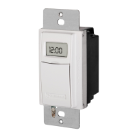
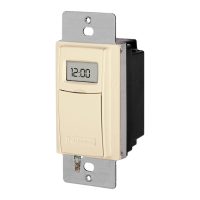
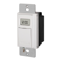
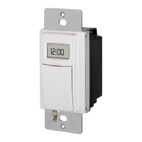
Self-Adjusting Wall Switch Timer
Turn off power at the service panel by REMOVING FUSE or
TURNING THE CIRCUIT BREAKER OFF.
Remove the existing wall switch.
Trim building wires to 7/16” as shown.
If a Single Switch Setup:
Connect one of the two wires
from the wall to the black wire
from the switch timer, using
the twist connectors provided.
Connect the other wire from
the wall to the blue wire from
the switch timer, using the
twist connectors provided.
NOTE: The RED wire is not used in single-switch installations.
Cap with a twist connector.
1.
2.
3.
a.
b.
Resistive (heater) 15 Amp, 120-277 VAC
Tungsten (incandescent) 15 Amp @ 120 VAC, 6 Amp @ 208-277 VAC
Ballast (fluorescent) 8 Amp @ 120 VAC, 4 Amp @ 208-277 VAC
Motors 1 H.P. @ 120 VAC, 2 H.P. @ 240 VAC
DC Loads 4 Amp @ 12 VDC, 2 Amp @ 28 VDC
•
•
•
•
•
Installation and User Instructions
MODEL ST01 Series
2 – Install the Switch Timer
Ratings
Before installing the switch timer into the wall, make sure the
supplied battery is installed and working.
Open the access door to reveal the battery tray, located below
the ON/OFF keypad.
If there is a pull tab at the battery tray, remove the tab to con-
nect the installed battery. Make sure battery tray is pushed
fully into place. Proceed to Step 6.
If the battery was supplied loose, use a flat screwdriver to pry
loose the battery tray.
Place the supplied “CR2” battery into the tray, observing +
and – markings on tray.
Replace the battery tray into the switch timer.
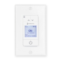
The display will initialize itself then flash “12:00 AM” in
MANual mode.
Press the ON/OFF button. The switch timer should “click.”
NOTE: If display doesn’t flash “12:00 am”, the battery may be
dead. Replace the battery before installing the switch timer.
1.
2.
3.
4.
5.
6.
7.
1 – Before Installing Switch Timer, Install and Check Battery
BLACK WIRE
BLUE WIRE
RED WIRE
(capped, not connected)
RED WIRE
BLUE WIRE
BLACK WIRE
WIRE FROM
“COMMON” OF
OLD SWITCH
DIAGRAM 1:
TYPICAL
EXISTING
2-SWITCH
SETUP
LOAD
NEUTRAL
3-WAY
MAIN SWITCH
WIRE “A”
“COMMON” TERMINAL
LINE
3-WAY
REMOTE SWITCH
WIRE “B”
WIRE “C”
DIAGRAM 2:
2-SWITCH SETUP,
TIMER INSTALL
RE-USING EXISTING
REMOTE 3-WAY SWITCH
LOAD
NEUTRAL
WIRE “A”
“COMMON” TERMINAL
LINE
3-WAY
REMOTE SWITCH
WIRE “B”
NOT USED
BLACK
TIMER
BLUE
RED
WIRE “C”
JUMPER
DIAGRAM 3:
2-SWITCH SETUP,
TIMER INSTALL USING
NEW SINGLE-POLE
REMOTE SWITCH
LOAD
NEUTRAL
WIRE “A”
LINE
SINGLE-POLE
REMOTE SWITCH
WIRE “B”
BLACK
TIMER
BLUE
RED
WIRE “C”
JUMPER
158ST13133
Observed Problem Possible Cause What to Do
Switch timer does not switch ON/OFF but
display looks normal.
Switch timer is not set in AUTO, RANDom, or
MANual mode.
Press MODE to select the operational mode you
want to use.
Switch timer won’t enter AUTO or
RANDom mode when you press MODE.
The time of day or timer settings have not
been set.
Make sure the time of day and at least one sched-
uled activity have been set.
Switch timer switches at incorrect times
or skips some of the programmed times.
Programmed schedule(s) are incorrect.
Press ON/OFF to review the settings and revise
them as necessary. See instructions at the left.
Switch timer is in RANDom mode, which var-
ies switching times up to ±20 minutes (to give
your home a “lived-in” look).
If you don’t want to keep the switch timer in
RANDom mode, press MODE to change to AUTO
mode.
The Astronomic and Specific switching times
are in conflict. For example, you’ve set ON to
DUSK and OFF at 8 pm, and due to seasonal
changes, DUSK has advanced to 8:30 pm.
NOTE: Your switch timer automatically skips
any conflicting ON event as summer ap-
proaches to prevent unwanted operation of
lights or other controlled devices. See “What
to Do” if you want to identify and remove
conflicting settings.
Complete the steps for setting the Time and
Date, then temporarily change the date to
June 21st.
Review the DAWN and DUSK settings by
pushing the ON/OFF button.
Make sure the specific ON or OFF time set-
tings won’t interfere with these DAWN and
DUSK times. Make changes as necessary.
When finished, change the Date setting back
to today’s date.
1.
2.
3.
4.
The lights or controlled devices don’t
match the programmed ON/OFF status
immediately after setting the time or
programming a schedule.
Switch timer does not “catch up” automati-
cally to the programmed load state. The status
of the switch timer will remain as is until it
comes to the next programmed ON/OFF time.
After entering your schedules or the time, then
returning to the AUTO mode, push the ON/OFF but-
ton to change the load state if necessary.
Load only operates when the remote
(3-way) switch is in one position, or the
switch timer ignores the remote switch.
The remote switch is wired incorrectly.
Recheck the wiring, especially for the jumper,
according to “If a 3-way Switch Timer” and “If a
Multiple Switch Timer Setup.”
The switch timer ignores a 3-way remote
switch even though it is wired correctly.
There is an excessive length of wire (more
than 100 feet), or there is buried wire to the
switch.
Eliminate the condition: either replace the buried
cable, do without the remote switch, or contact
Intermatic Customer Service for more options.
The remote switch is not functioning properly
or worn out.
Replace the remote switch.
The load turns off immediately after being
turned on.
The remote switch or switch timer is wired
wrong.
There is an excessive length of wire
(greater than 100 feet)
There is buried wire to the remote switch.
The switch timer is not functioning properly.
•
•
•
•
If the problem persists with the switch timer’s red
wire disconnected or with a remote switch tempo-
rarily connected right at the switch timer, replace
the non-functioning switch timer. Otherwise, try
the above suggestions.
The battery tray is difficult to replace.
Battery is not seated in the tray.
The tray is misaligned.
The contact tabs of the tray are bent.
•
•
•
Seat the battery in the tray, then reinstall.
The switch timer operation is sluggish or
not switching ON/OFF at all.
Though the “BATT” message is not being
displayed, the battery is getting weak.
Replace the battery. To test the battery, press the
ON/OFF button. The timer should “click.”
Timer shows ON but the light or other
controlled device is OFF.
The light or controlled device itself may be
switched OFF.
Make sure the light or controlled device is
switched ON and plugged in.
Troubleshooting Guide
LIMITED ONE-YEAR WARRANTY
If within one (1) year from the date of purchase, this product fails due to a defect in material or workmanship, Intermatic Incorporated will repair or replace it, at its sole option, free of charge. This warranty is
extended to the original household purchaser only and is not transferable. This warranty does not apply to: (a) damage to units caused by accident, dropping or abuse in handling, acts of God or any negligent use;
(b) units which have been subject to unauthorized repair, opened, taken apart or otherwise modified; (c) units not used in accordance with instructions; (d) damages exceeding the cost of the product; (e) sealed
lamps and/or lamp bulbs, LED’s and batteries; (f) the finish on any portion of the product, such as surface and/or weathering, as this is considered normal wear and tear; (g) transit damage, initial installation costs,
removal costs, or reinstallation costs.
INTERMATIC INCORPORATED WILL NOT BE LIABLE FOR INCIDENTAL OR CONSEQUENTIAL DAMAGES. SOME STATES DO NOT ALLOW THE EXCLUSION OR LIMITATION OF INCIDENTAL OR CONSEQUENTIAL
DAMAGES, SO THE ABOVE LIMITATION OR EXCLUSION MAY NOT APPLY TO YOU. THIS WARRANTY IS IN LIEU OF ALL OTHER EXPRESS OR IMPLIED WARRANTIES. ALL IMPLIED WARRANTIES, INCLUDING THE
WARRANTY OF MERCHANTABILITY AND THE WARRANTY OF FITNESS FOR A PARTICULAR PURPOSE, ARE HEREBY MODIFIED TO EXIST ONLY AS CONTAINED IN THIS LIMITED WARRANTY, AND SHALL BE OF
THE SAME DURATION AS THE WARRANTY PERIOD STATED ABOVE. SOME STATES DO NOT ALLOW LIMITATIONS ON THE DURATION OF AN IMPLIED WARRANTY, SO THE ABOVE LIMITATION MAY NOT APPLY TO
YOU.
This warranty service is available by either (a) returning the product to the dealer from whom the unit was purchased, or (b) mailing the product, along with proof of purchase, postage prepaid to the authorized
service center listed below. This warranty is made by: Intermatic Incorporated/After Sales Service/7777 Winn Rd., Spring Grove, Illinois 60081-9698/815-675-7000 http://www.intermatic.com Please be sure to wrap
the product securely to avoid shipping damage.
INTERMATIC INCORPORATED
SPRING GROVE, ILLINOIS 60081-9698
Electrical shock hazard. Risk of injury or death. Remove electrical power
at service panel before installing.
Risk of fire or burns from used battery. Do not recharge, disassemble, heat
above 100˚ C, crush, or incinerate the lithium battery. Keep battery out of
reach of children. Replace only with Panasonic type CR2 or equivalent
CR2 battery approved by Underwriters Laboratories (UL). Use of a differ-
ent battery type may present a risk of fire or explosion upon disposal of
battery.
Risk of fire. Do not use timer to control devices that could have danger-
ous consequences due to inaccurate timing, such as sun lamps, sauna,
heaters, crock pots, etc.
•
•
•
WARNING
Follow local electrical codes during installation.
Risk of timer damage due to leakage if weak battery is not replaced promptly.
Dispose of used battery promptly per local regulations.
•
•
•
NOTICE