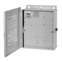
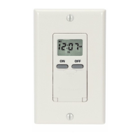
INTERNAL WIRING
TROUBLE SHOOTING
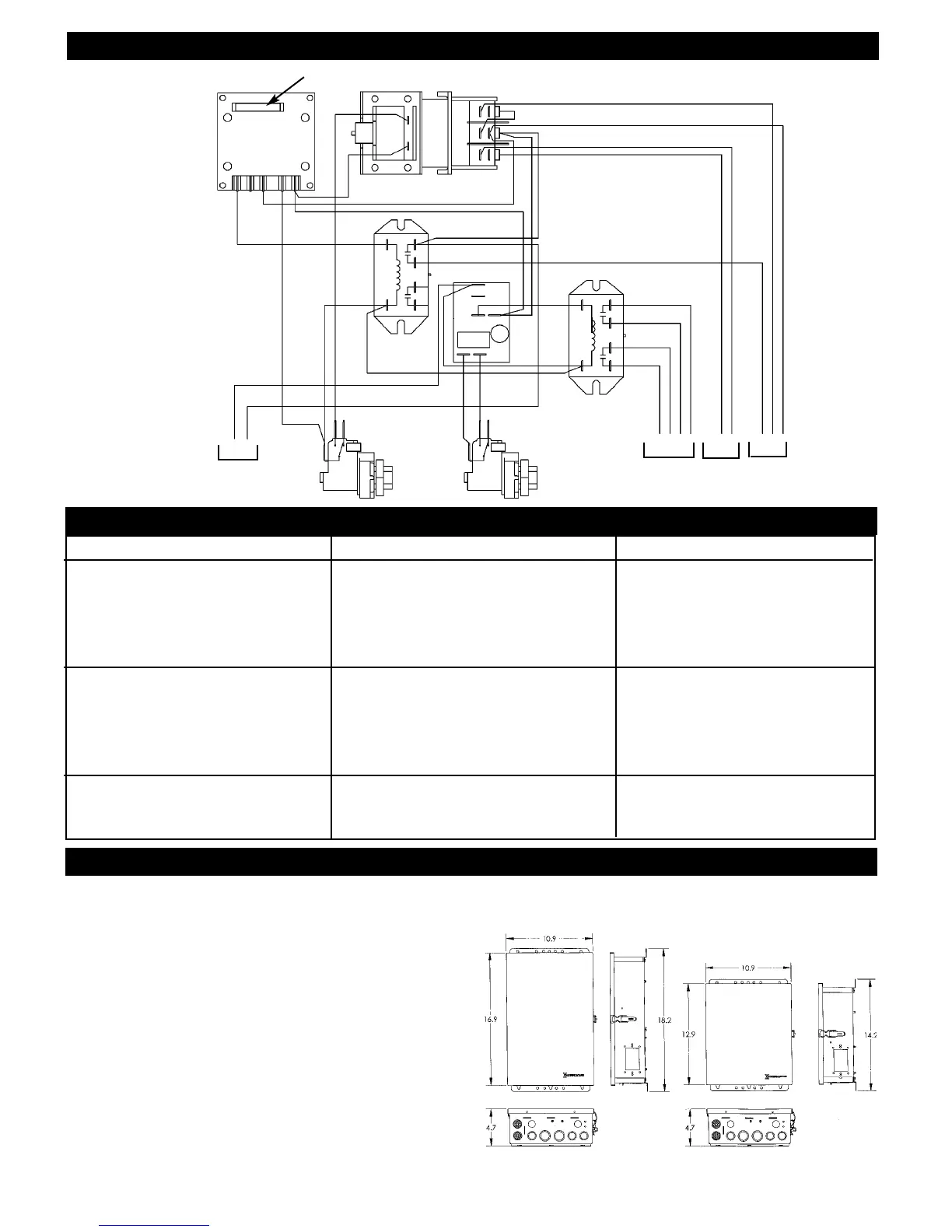
NOTES AND SPECIFICATIONS
SYMPTOM CAUSE(S) CORRECTIVE ACTION
1. Pump will not turn ON/OFF or 1a. Air hose disconnected. Check hose connections.
operate on low speed only. 1b. Defective air button. Replace air button - see note 1.
1c. Water in air hose. Blow-out air hose - see note 2.
1d. Defective pulse switch. Replace pulse switch - see note 2.
1e. Defective relay. Replace relay - see note 3.
1f. Air button is too far. Install larger air button.
2. Timer is not turning Pump 2a. Defective timer. Replace timer.
ON/OFF for daily filtration. 2b. Defective relay. Replace relay.
2c. Timer is set to permanent Set timer to AUTO.
ON/OFF.
2d. No program in timer’s memory. Set program - see instructions.
2e. Dead memory hold-up battery . Replace battery.
3. Pump turns ON/OFF by itself. 3a. Defective pulse switch Replace pulse switch.
3b. W
ater in air hose
Blow-out air hose - see note 2.
3c. Changing air pressure in air hose
Reroute air hose.
1. An air button with ruptured seal or bellows inside, will
not produce sufficient air pressure to operate the
momentary air switch and could lead to total
br
eak-do
wn.
2. Water in air hose will damage the pulse switch and it is
caused by a faulty air button (see note 1above) or
condensation. In either case, it must be drained and the
cause f
ound and cor
r
ected
.
To reduce condensation,
protect the air hose from exposure to direct sun, ice or
frequent temperature fluctuations.
3.
A defective relay is either due to contact or coil failure.
Contact failure is caused by over-load or cross-wiring
and coil f
ailur
e is caused by 240 volt connected across
the 120 v
olt coil or per
manentl
y a
pplied 120 v
olt. (T
he
relay is designed for intermittent duty only).
Permanently applied 120 volt could be the result of
w
a
ter in the air hose (see note 2 a
bo
ve) or spa cover
placed over (and depressing) the air button. In any case,
the cause m
ust be f
ound
,
cor
rected and the relay replaced.
3
PULSE
SWITCH
#1
PULSE
SWITCH
#2
MEMOR
Y
HOLD-UP
BATTERY
TIMER
LINE
NEUTRAL
120 V
SUPPLY
WHITE
BLACK
RED
YELLOW
RED
YELLOW
BLUE
BLACK
GREY (LOW SPEED)
BLUE (HIGH SPEED)
BROWN (FREEZE PROT.)
AUX.
BLOWER PUMP
RELA
Y
#2
RELA
Y
#1
STEPPER RELA
Y