EasyManua.ls Logo

Intermatic RC2403RT - User Manual

Intermatic RC2403RT
4 pages
Print Icon
To Next Page IconTo Next Page
Loading...
INSTALLATION
OPERATION &
SERVICE MANUAL
RC2000 SERIES
REMOTE CONTROLS
AIR OPERATED CONTROL FOR SPAS
Suitable for Pool Equipment Control and for Direct Connection of Underwater Lights
Model: RC2403RT
BUTTON #1: PUMP AND BLOWER - SEQUENTIAL
1 H.P. - 120V., 2 H.P. - 240 V. EACH CIRCUIT
BUTTON #2: AUX. CIRCUIT - DOUBLE POLE SINGLE THROW
1.5 H.P. - 120V., 3 H.P. - 240V., 10 AMP. TUNGSTEN - 120V.
DANGER! To Reduce the Risk of Injury:
...do not per
mit small children to operate the control or use the Pool/Spa unless they are closely supervised at all times.
...test GROUND FAULT protection regularly. If it fails to reset, DO NOT USE THE POOL or SPA! Contact a qualified service
technician.
...always disconnect electricity before servicing this Control or the equipment connected to it. THIS CONTROL IS NOT TO BE
USED AS A POWER DISCONNECT.
IMPORTANT SAFETY INSTRUCTIONS
When installing and operating this Product and other associated equipment, basic safety precautions should always be followed,
1. This Control must be installed by a qualified person, according to National and Local Electrical Codes.
2. Install this Control not less than 5 feet (3 meters in Canada) from inside edge of pool. USE COPPER CONDUCTORS ONLY.
3. Do not exceed the maximum ratings of individual components, wiring devices, and current carrying capacity of conductors.
4. For Control grounding, bonding, installing and the wiring of underwater lights, refer to Article 680 of the National Electrical Code or Article
68 of the Canadian Electrical Code.
5. The Control should not operate any equipment which would cause bodily injury or property damage should it be activated
unexpectedly.
READ, FOLLOW AND SAVE THIS INSTRUCTION MANUAL
GENERAL INFORMATION
This Air Switch is designed to control three separate
pieces of equipment with two air buttons. It can control
safely, without electricity at the spa side, for example, a
pump (120V. or 240V., single or two speed) blower and
an auxiliar
y equipment. Eac
h time pr
essur
e is a
pplied to
air button #1 the pump and/or blower will operate in the
sequence shown below. In addition, the timer will
automa
tically turn the pump ON/OFF (low speed if two
speed pump) for daily filtration.
To heat the spa water on a pre-selected time schedule, set
the thermostat to the desired temperature and set the
timer accordingly.
Button #2 is provided to operate an additional auxiliary
equipment for example, a jet or booster pump, lights or a
sanitizer.
EQUIPMENT Sequence 1 (Home Position) Sequence 2 Sequence 3 Sequence 4
Filter Pump
One Speed Timer ON/OFF ON ON OFF
Low/High Speed
T
imer Low/Of
f
High
High
Low
Blower OFF OFF ON ON
1
Question and Answer IconNeed help?

Do you have a question about the Intermatic RC2403RT and is the answer not in the manual?

Intermatic RC2403RT Specifications

General IconGeneral
BrandIntermatic
Voltage120V
Amperage15A
Frequency60 Hz
ProgrammableYes
DisplayDigital
Battery BackupYes
MountingWall

Summary

General Information and Safety

Product Overview and Operation

Describes the air switch function for controlling spa equipment, including pump, blower, and auxiliary devices.

Button #1 Sequence

Details the sequential operation of the pump and blower using air button #1.

Button #2 Auxiliary Control

Explains the use of air button #2 for controlling additional auxiliary equipment.

Critical Safety Warnings

Highlights danger of injury, child supervision, ground fault protection, and power disconnect.

Important Installation Safety

Provides essential safety precautions for installation and operation by qualified persons.

Installation and Operation Instructions

Installation Guide

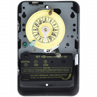
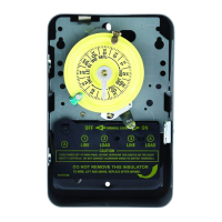
Step-by-step instructions for wiring, grounding, and connecting air hoses.

Timer Programming

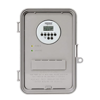
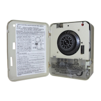
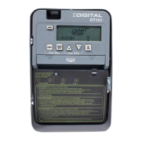
Instructions for setting the time of day and ON/OFF schedules for the timer.

Automatic Operation Override

Guidance on temporarily or permanently overriding automatic timer functions.

Equipment Sequence Operation

Details the sequence of jets and blower activation via air button #1.

Internal Wiring and Troubleshooting

Internal Wiring Diagram

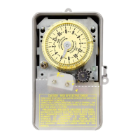
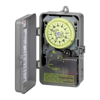
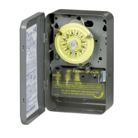
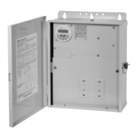
Visual representation of the control's internal electrical connections.

Troubleshooting Symptoms and Solutions

Lists common issues, their causes, and corrective actions for the control.

Technical Notes and Specifications

Important notes on air button function, water in hoses, and relay limitations.

Wiring Diagrams and Warranty

Wiring Diagrams for 120 V;240 V Systems

Diagrams illustrating connections for 120V and 240V systems with various pump configurations.

One Year Limited Warranty

Details the terms and conditions of the product's one-year limited warranty.

Related product manuals