158TS11854
Note:
1. ALL MARKINGS TO BE PER
INTERMATIC APPROVED
ARTWORK.
DR: SRB 8/24/2004 ITEM PART NUMBER DESCRIPTION QTY
ORIG:
INTERMATIC INCORPORATED
CHKD: GLM 8/24/2004
SCALE: FULL
NAME:
INST SHT - DOOR, T8805P101C - ENG
APPROVED MATL: WHITE PRESSURE SENSITIVE STOCK
1 RELEASED
T
O ELEC. DA
T
A T8805P101C
GLM 8/24/2004 FINISH: BLACK PRINTING INK
LET REVISION DATE/BY MODEL
SUPERSEDES
HEAT TREAT
+1/32
3 7/8
TOOL
T
OL:
BOXED
T
OLERANCES
ARE FOR LIFE-OF-TOOL DEVIATION ONLY.
DO NOT USE FOR RE-TOOLING.
DIM TOL. : DECIMALS (UNLESS OTHERWISE SPECIFIED) - TWO PLACE (.00)
+
.015 - THREE PLACE (.000)
+
.005
ANGLES
+
30 MINUTES - ALL DIMENSIONS MUST BE MET BEFORE PLATING.
R (OPTIONAL)
D17
+1/32
6 3/4
SEE B/M FOR ALL PART NUMBERS & QUANTITIES
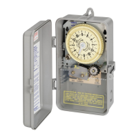
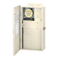
MODEL: T8805P101C
PROGRAM TIME SWITCH WITH
14-DAY "SKIPPER
®
" WHEEL
FOR UP TO 60 OPERATIONS PER DAY
SWITCH RATING: SINGLE POLE SINGLE THROW
15 AMP., 1/2 H.P.125 VOLTS A.C.
CLOCK MOTOR: 125 VOLTS - 60 HZ.
PROGRAMMING INSTRUCTIONS:
1. TO SET FIRST ZONE: For watering, push gold pin into slot on yellow
dial at desired ON time. For each 12 minutes of additional watering
add one pin WITHOUT skipping a slot.
2. TO CHANGE ZONES: Leave one blank slot on yellow dial after ON
line (gold pin), and valve will automatically advance to next zone.
3. TO SET ADDITIONAL ZONES: Repeat steps 1 and 2. REMEMBER
to leave blank space between zones
4. TO SET TIME OF DAY: Turn yellow dial CLOCKWISE, until correct
line is at end of silver time pointer. Do NOT turn silver pointer.
5.
TO SKIP DAYS: Turn black skipper wheel COUNTER-CLOCKWISE
until todays day is in front of "14" arrow. Press pins DOWN on days
of NO watering. The skipper wheel must have all pins UP for daily
watering.
6. PUT SELECTOR SWITCH IN AUTO: This switch can be used to turn
the system ON or OFF for manual operation without affecting the set
program.
IMPORTANT NOTICE: Use the one silver pin that is located at Midnight
on the yellow dial, it advances the skipper wheel automatically. Do NOT
use multiple silver pins.
Follow The National Electrical Code and local code requirements when
installing this time switch.
CAUTION: Always disconnect power at main panel before servicing
this Switch or the equipment it controls.
INTERMATIC INCORPORATED
SPRING GROVE, ILLINOIS 60081-9698
158TS11854
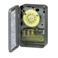
TIME
POINTER
DIAL
SKIPPER
AUTO
TIME
DAY
SELECT
OR
SWITCH
FIGURE 1
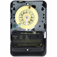
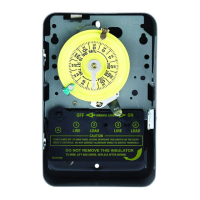
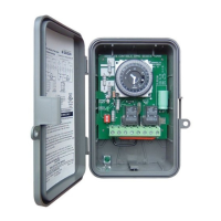
WIRING DIAGRAM
GROUND TO
120 VOLT
POWER
SUPPLY
NOT FOR DIRECT PUMP CONTROL
TO
SOLENOID
COMMON CLOCK
NEUTRAL
(WHITE)
LINE
(BLACK)
LR3730