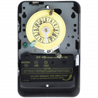
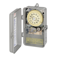
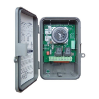
MODEL: T7801B
SEVEN-DAY DIAL TIME SWITCH
4 POLE; Two Normally Open - Two Normally Closed
MINIMUM “ON” TIME 3-1/2 HR. UP TO 3-1/2 DAILY ON-OFF OPERATIONS
CONTACT RATINGS:
40 AMP. RESISTIVE EACH POLE 120V-480V AC.
40 AMP. INDUCTIVE, TUNGSTEN EACH POLE 120V, 208V, 240V, OR
277V AC. 1000 VA PILOT DUTY EACH POLE 120V - 277V AC.
24 FLA, 144 LRA (2 HP) - 120V AC.; 28 FLA, 168 LRA (5 HP) - 240V AC.
CLOCK MOTOR: 125 VOLTS - 60 HZ.
FOR REPLACEMENT MOTOR, ORDER WG1600
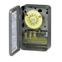
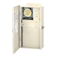
WIRING INSTRUCTIONS
This Time Switch can be wired to control one to four circuits simultaneously on a seven
day schedule. Clock motor voltage may be other than load voltage, but must be as
specified. For terminal markings, internal wiring and contact arrangements refer to wiring dia-
gram above. To form the common poles of a DOUBLE POLE DOUBLE THROW switch, if
required, install jumpers (extend supply wires) between terminals 1-6 and 3-8. Use solid or
stranded COPPER
only wire with insulation to suit installation. See table for gauge selection.
To make power connections remove 1/2 inch of insulation from wire ends. Insert bare ends
of wire under the pressure plate of terminals. Use 3/16 or larger screw driver to tighten
terminal screws firmly.
REPLACE FRONT INSULATOR BEFORE TURNING
ON ELECTRICITY.
PROGRAMMING INSTRUCTIONS
1. TO SET “ON” TIMES, place bright ON trippers against edge of CLOCK-DIAL at
day-of-week and time-of-day when
“ON” operations are desired. Tighten tripper
screws securely.
2.
T
O SET “OFF” TIMES,
place dark OFF trippers against edge of CLOCK-DIAL at
times when
“OFF” operations are desired. Tighten tripper screws securely.
3.
TO SKIP DAYS, omit trippers for the day(s) automatic operations is/are not required.
4.
T
O SET DIAL
T
O TIME-OF-DA
Y
,
turn dial CLOCKWISE and align the exact day-of-
week and time-of-day (AM or PM) on dial with the
TIME POINTER. Some allowance
may be required to compensate for gear backlash.
CAUTION: DO NOT MOVE POINTER OR FORCE DIAL COUNTERCLOCKWISE.
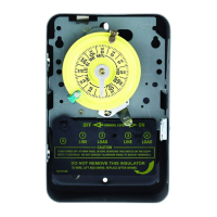
OPERATING INSTRUCTIONS
• TO OPERATE SWITCH MANUALLY
: Move MANUAL LEVER below CLOCK-DIAL
left or right as indicated by arrows.
This will not af
fect next automatic operation.
• IN CASE OF POWER FAILURE OR TO ADVANCE/RETARD TIME: Reset time-of-
day, see step 4 of programming instructions.
DISCONNECT ELECTRICITY
BEFORE
ANY
BEHIND-THE-INSULA
T
OR WORK.
INTERMA
TIC INCORPORA
TED
SPRING GROVE, ILLINOIS 60081-9698
158TS10981
PRESSURE PLATE
TERMINAL SCREW
MAKE SURE WIRE
INSULATION CLEARS
PRESSURE PLA
TE
MINIMUM
COPPER
WIRE SIZE
(AWG)
MAX.
LOAD
(AMP)
MIN.
INSUL-
ATION
TEMP(°C)
75°C INSULATION MAX. MOTOR
LOAD (HP)
SINGLE PHASE
3 PHASE
120 V
.
240 V.
208 V.
240 V
.
14
12
10
8
15
20
30
40
60
60
60
75
1/2
1
2
-
2
2 1/2
3
5
N/A
N/A
120 V
60 HZ
TO
LOADS
SUPPLY
WIRING DIAGRAM
GROUND
SCREW
CLOCK
MOTOR
LR3730
158TS10981 8/6/04 10:43 AM Page 1