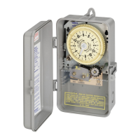
MODEL: T1471BR
24 HOUR DIAL TIME SWITCH WITH ‘’SKIPPER ’’
FOUR POLE SINGLE THROW
40 AMP. RESISTIVE,EACH POLE 120-480V. AC;
40 AMP
. INDUCTIVE TUNGSTEN OR 1000 V.A. PILOT DUTY EACH POLE 120-277 V. AC;
2 H.P. (24 FLA) - 120 V. AC; 5 H.P. (28 FLA) - 240 V. AC SINGLE PHASE
7 1/2 H.P. (28 FLA) - 208V. A.C.; 10 H.P. (28 FLA) -240V. A.C.; THREE PHASE.
®
INDEPENDENTLY WIRED CLOCK MOTOR: 110-125V. 60 HZ.
CLOCK MOTOR VOLTAGE AND CYCLE MUST BE AS SPECIFIED. TO
ORDER REPLACEMENT, INDICATE PART NO. (WG--) ON MOTOR
COVER.
wire with insulation to suit installation. See gauge selection table for nor-
mal service applications. To make power connections see illustration
below. Replace front insulator before turning on electricity. Motor
voltage and cycle (Hz). must be as specified above.
PRESSURE PLATE
TERMINAL SCREW
MAKE SURE WIRE
INSULATION CLEARS
PRESSURE PLATE
MINIMUM
COPPER
WIRE SIZE
(AWG)
MAX.
LOAD
(AMP)
MIN.
INSUL-
ATION
TEMP(°C)
75
°
C INSULATION MAX. MOTOR
LOAD (HP)
SINGLE PHASE
3 PHASE
120 V. 240 V. 208 V.
240 V.
14
12
10
8
15
20
30
40
60
60
60
75
1/2
1
2
-
2
2 1/2
3
5
3
5
71/2
10
3
4
5
7/12
PROGRAMMING INSTRUCTIONS
•
•
•
OPERATING INSTRUCTIONS
•
•
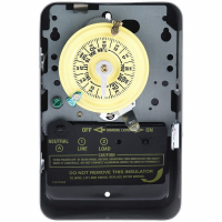
TO SET “ON” AND “OFF” TIMES: Hold trippers against edge of CLOCK-DIAL,
pointing to time (AM or PM) when ON and OFF operations are desired, tighten
tripper screws firmly. See caution below. For additional tripper pairs on CLOCK-
DIAL order 156T1978A.
TO SET TIME-OF-DAY: Pull CLOCK-DIAL outward. Turn in either direction and
align the exact time-of-day on the CLOCK-DIAL (the time now, when switch is
being put into operation) TO TIME POINTER. DO NOT MOVE THE POINTER.
TO SKIP OPERATION(S) ON SELECTED DAY(S): Insert SKIPPING SCREW(S)
in SKIPPER WHEEL for day(s) automatic operation(s) is/are NOT required.
Tighten screws firmly. Move MANUAL LEVER to “OFF” and rotate SKIPPER
WHEEL to locate correct day-of-week opposite DAY ARROW--”YESTERDAY” if
ON/CUTOUT TRIPPER has not yet advanced wheel “TODAY” if it has.
TO OPERATE SWITCH MANUALLY: Move MANUAL LEVER bellow CLOCK-
DIAL left or right as indicated by arrows. This will not effect next operation.
CAUTION: TO AVOID SLOW TRIPPER ACTION FAILURE, DO NOT OPERATE
SWITCH MANUALLY NOR PLACE A TRIPPER 4 HOURS PRIOR TO ON/OFF
CUTOUT TRIPPER SWITCHING.
IN CASE OF POWER FAILURE, reset CLOCK-DIAL to proper time-of-day. See
programming instructions.
INTERMATIC INCORPORATED
SPRING GROVE, ILLINOIS 60081-9698
158TS11732
TIME
POINTER
TIME
DIAL
OFF
TRIPPER
MANUAL
LEVER
SKIPPING
SCREW
SKIPPER
WHEEL
DAY
ARROW
ON/CUTOUT
TRIPPER
WIRING INSTRUCTIONS:
To wire switch follow diagram above.
Use solid or stranded COPPER
LR3730
120 V
60 HZ
TO
LOADS
SUPPLY
(4PST)
WIRING DIAGRAM
GROUND
SCREW
CLOCK
MOTOR
A
7
B
5
6
1
2
8
3
4
158TS11732 5/6/04 10:26 AM Page 1