OPERATION
TROUBLESHOOTING
TO SET FILTER PUMP TIME SWITCH, follow
instructions on the right. The length of the daily filtration/
heating cycle depends on many variables such as size, shape,
geographic location of the pool, water chemistry, type of
pool equipment, usage and season of year. If not sure,
contact your local pool service professional for advice.
THE FIREMAN SWITCH (Heater Protection Mechanism),
if required, is factory set and shuts OFF the heater 20
minutes before the Time Switch turns OFF the filter pump.
The Fireman Switch requires no setting or service.
SYMPTOM
1.
T
ime Switc
h will not keep
time but dial is turning.
2. Time Switch Dial stops
a
t ON or OFF tripper.
3.
Dial stops after s
witc
h
tur
ns OFF
.
4.
Load is ON a
t all times -
dial is tur
ning
.
5. Dead clock motor. (Clock
motor g
ear
s do not r
otate).
CAUSE(S)
1a.
F
r
equent power outages
1b. Wrong voltage/cycle
1c
.
Loose c
loc
k motor connections
2a. Loose tripper
2b
. Bent dial
2c. Defective motor
3a.
LINE leads ar
e connected
to LO
AD ter
minals
4a.
W
elded contacts
4b
.
T
w
o ON tr
ippers and
no OFF tripper on dial
4c. Defective mechanism
5a. Defective clock motor
(open coil due to lightning or sur
g
e)
5b
. Loose clock motor connections
5c. Wrong voltage
CORRECTIVE ACTION
Reset dial
Chang
e clock motor
Check connections
Chec
k/c
hang
e tr
ipper
Chec
k/c
hange mechanism
Change clock motor
Reverse LINE and LOAD connec-
tions
Change mechanism
Change tripper
Chang
e mechanism
Chang
e c
loc
k motor
Check connections
Change clock motor
3
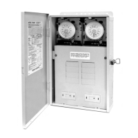
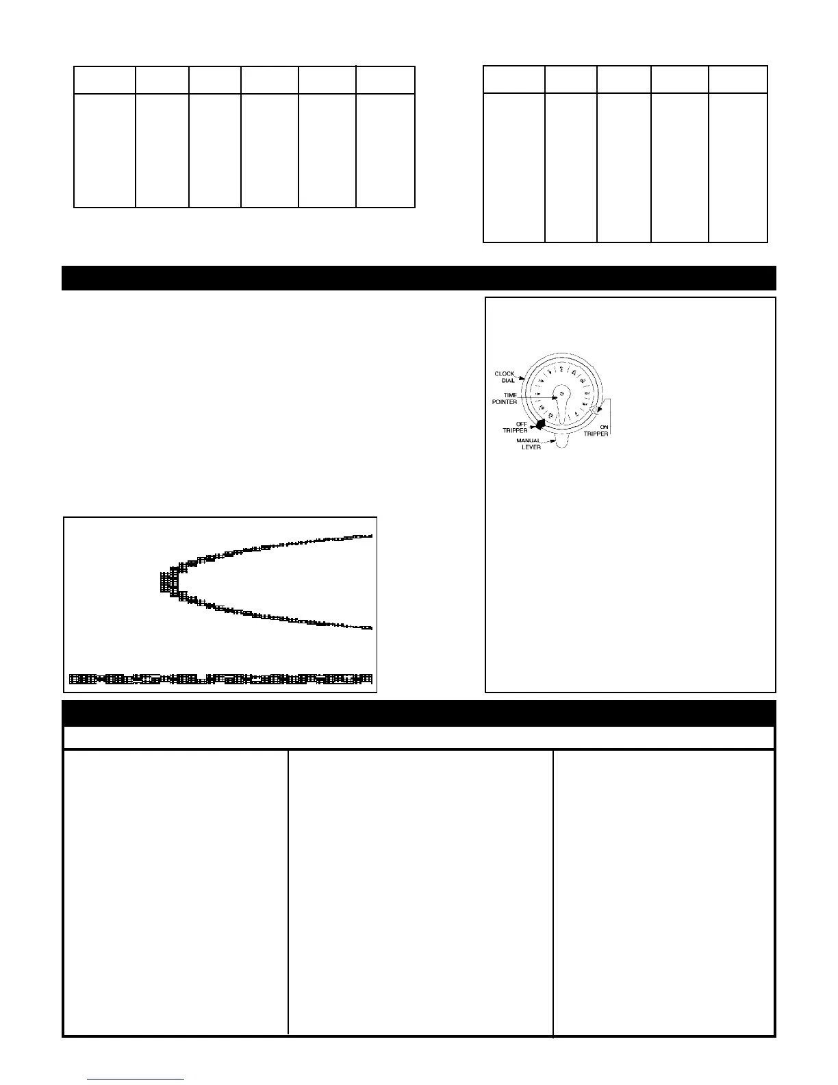
TIME SWITCH OPERATING
INSTRUCTIONS
1. TO SET "ON" AND
"OFF"
TIMES:
Hold
TRIPPERS against edge of
CLOCK-DIAL, pointing
to time (AM or PM) when
ON and OFF operations
are desired. Tighten tripper
screws firmly.
2. TO SET TIME-OF-DAY:
Pull CLOCK-DIAL outward. Turn in either direction
and align the exact time-of-day on the CLOCK-DIAL
(the time now, when switch is being put into operation)
to the pointer.
• TO OPERATE SWITCH MANUALLY: Move
MANUAL LEVER below CLOCK-DIAL left or
right as indicated by arrows. This will not affect
the next operation.
• FOR MORE THAN ONE DAILY ON-OFF
OPERATION:
Place additional tripper pairs on
CLOCK-DIAL (order 156T1978A).
• IN CASE OF POWER FAILURE: Reset CLOCK-
DIAL to proper time of day. See step 2 above.
Figure 2
Distance* 2#6AWG 2#8AWG 2#10AWG 2#12AWG 2#14AWG
Feet
5 Ft. 12V 12V 12V 12V 12V
30 Ft. 12V 12V 12V 13V 13V
60 Ft. 12V 12V 13V 13V
90 Ft. 12V 13V 13V
120 Ft. 13V 13V
150 Ft. 13V 13V
180 Ft. 13V
210 Ft. 13V
240 Ft. 13V
* Length of run to light from transformer.
Distance* 2#6AWG 2#8AWG 2#10AWG 2#12AWG
Feet
5 Ft. 12V 12V 12V 12V
10 Ft. 12V 12V 12V 13V
20 Ft. 12V 12V 13V 13V
30 Ft. 12V 13V 13V 14V
40 Ft. 13V 13V 14V
50 Ft. 13V 13V 14V
60 Ft. 13V 14V
70 Ft. 13V 14V
80 Ft. 13V 14V
90 Ft. 14V
100 Ft. 14V
110 Ft. 14V
* Length of run to light from transformer.
120 Volt Primary Input - 300 Watt Output
120 Volt Primary Input - 100 Watt Output
GUIDELINES FOR WIRE SIZE PER LENGTH
 Loading...