108 109
Material Specification p 222 Refer to the Planning Section from p 168 onwards for help with planning and design
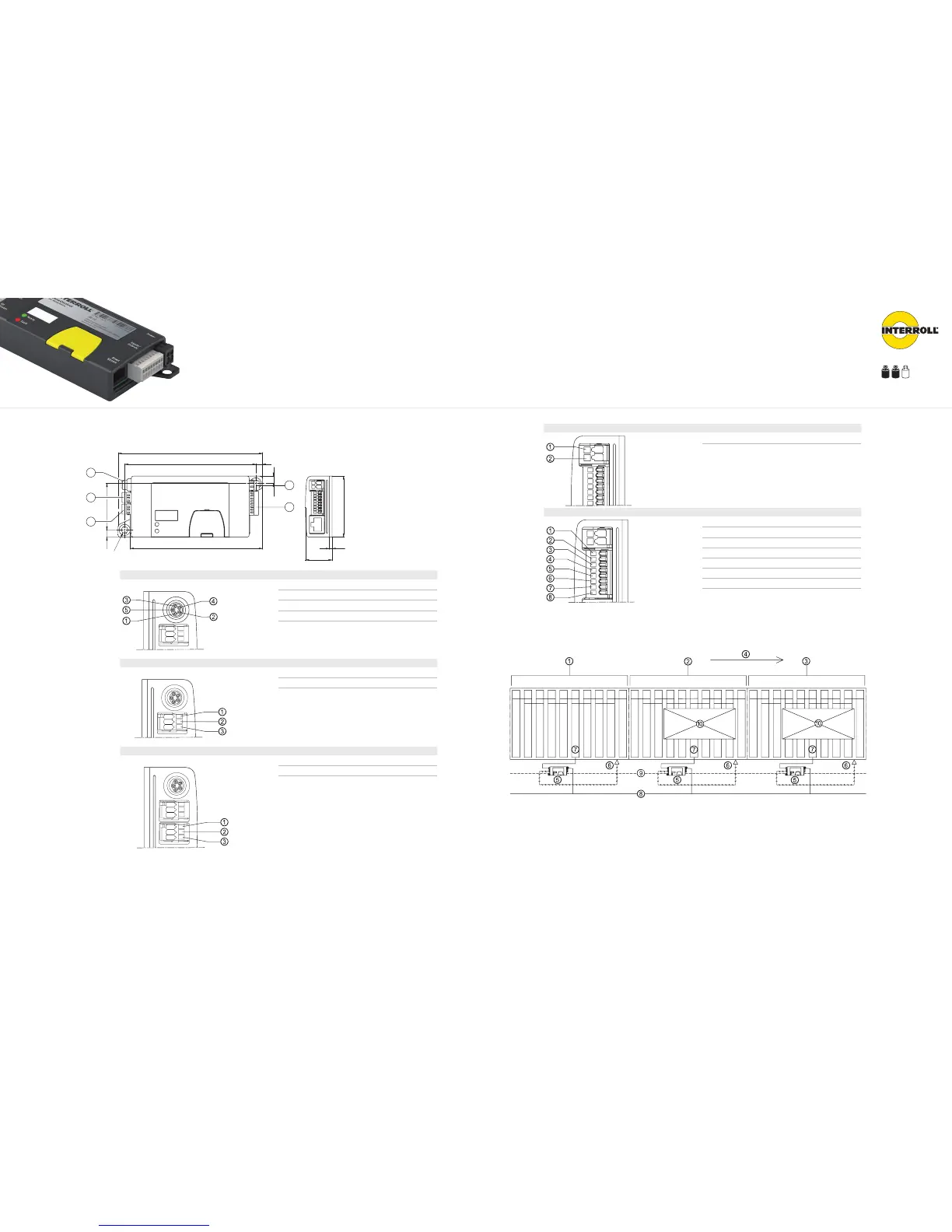
Dimensions and Connections
6.5
6.5
2.5
6
118
24
108
Ø 6
42
1
2
3
5
4
Pos. 1
RollerDrive Connection
1 +24 V DC
2 Direction of rotation
3 Earth
4 Fault input
5 Analogue speed output
Pos. 2
Start sensor
1 +24 V DC
2 Sensor signal input
3 Earth
Pos. 3
Zone sensor
1 +24 V DC
2 Sensor signal input
3 Earth
Pos. 4
Power
1 Earth
2 +24 V DC
Pos. 5
Inputs/Outputs
1 Start signal for 2nd RollerDrive in zone
2 Free travel signal
3 Speed (central)
4 Direction of rotation (central)
5 Fault output
6 Zone status
7 Zone start
8 Zone stop
Construction
Fig.: Wiring diagram for ZoneControl for 3 conveyor zones
1 Zone 1
2 Zone 2
3 Zone 3
4 Conveyor direction
5 ZoneControl
6 Zone sensor
7 RollerDrive
8 +24 V DC voltage supply
9 Peer-to-peer connection
10 Material to be conveyed
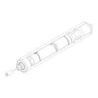
ZoneControl
DriveControl
ZoneControl
The accumulation conveyor logic for RollerDrive EC310
DriveControls Overview p 100 RollerDrive EC310 p 88 RollerDrive EC310 IP66 p 96