195
GS
SAVE THESE INSTRUCTIONS
(195GS) SAND FILTER PUMP ENGLISH 7.5” X 10.3” PANTONE 295U 06/20/2016
English
Page 7
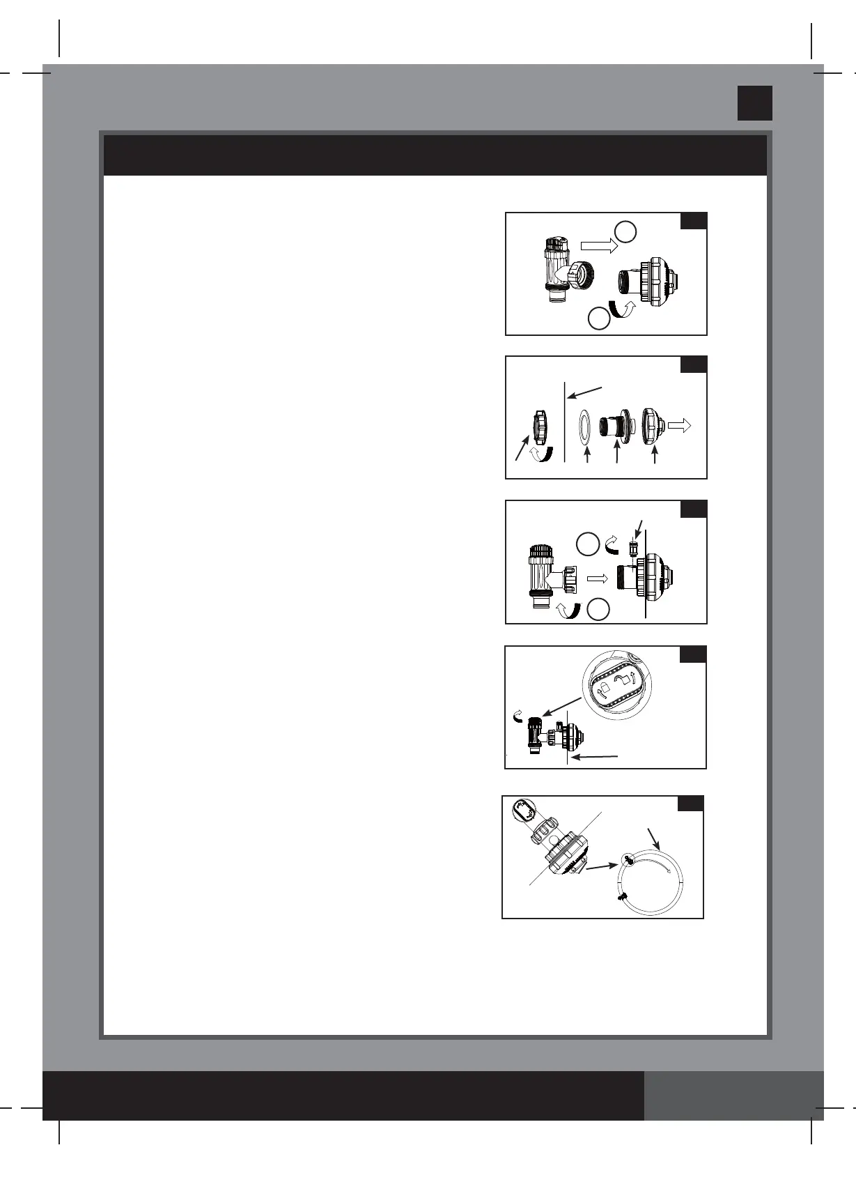
POOL INLET - NOZZLE & PLUNGER VALVE SETUP (optional)
1.
In a counter-clockwise motion unscrew
plunger valve union from the inlet threaded
air connector
(42)
(see drawing 5)
. Be
careful not to lose the step rubber
washer
(23)
. Place the plunger valve on
the ground in a safe place.
2.
In a counter-clockwise motion unscrew the
strainer nut
(24)
from the inlet threaded air
connector
(42)
. Leave the flat washer
(25)
on the connector
(42)
.
3.
Install the nozzle and plunger valve at the
upper position of pool inlet.
From the inside
of the pool liner insert the nozzle union
(27 & 42)
into one of the pre-cut holes with
the washer remaining on the connector to
be placed against the inside of the liner
wall.
4.
Before assembly, lubricate the threads with
a petroleum jelly. Then, with the flat side
of the strainer nut
(24)
facing the outside
wall of the liner in a clockwise motion screw
the strainer nut
(24)
back onto the inlet
threaded air connector
(42) (see
drawing 6)
.
5.
Finger tighten the adjustable pool inlet jet
nozzle
(27)
and the strainer nut
(24)
onto
the inlet threaded air connector
(42)
.
6.
Grasp the plunger valve assembly. Make
sure the step washer
(23)
is in place.
7.
Screw the air jet valve
(41)
over the inlet
threaded air connector
(42)
.
NOTE:
Make
sure the air jet valve is securely tighten
and facing up. In a clockwise motion screw
the plunger valve union back onto the inlet
threaded air connector
(42) (see
drawing 7)
.
8.
In a clockwise motion turn the plunger valve
handle to close position. Ensure the
plunger valve is securely closed. This will
prevent water from flowing out during filling
of the pool
(see drawing 8)
.
9.
Adjust the direction of nozzle head pointing
away from the pool outlet for a better
circulation result
(see drawing 9)
.
10.
The pool liner is now ready to fill with
water. Consult the above-ground-pool
owner’s manual for filling instructions.
5
2
1
7
1
2
8
INSIDE
LINER WALL
9
WATER
FLOW
POOL
6
25
42
27
INSIDE LINER
WALL
24
41