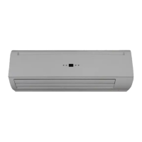
Do you have a question about the Intramech SWC-04-V-ECM and is the answer not in the manual?
| Brand | Intramech |
|---|---|
| Model | SWC-04-V-ECM |
| Category | Air Conditioner |
| Language | English |
Provides overall unit specifications and model series details.
Details specific performance data for SWC-V-EC series models.
Information on coil dimensions and construction for 2-pipe systems.
Detailed cooling and heating capacity data for 2-pipe systems.
Visual representations of unit dimensions for various models.
Details on valve dimensions and differential pressure characteristics.
Step-by-step guide for installing the main unit.
Guidelines for choosing the optimal installation site for the unit.
Specifies the dimensions for the unit's mounting plate.
Instructions for securely mounting the unit's support plate.
Procedures for creating the condensate drain hole.
Steps for physically attaching the unit to the mounting plate.
Guidelines for correctly installing the condensate drainage system.
Procedures for unit maintenance and initial setup.
How to access the unit by opening the grille cover.
Steps for disassembling the unit's front cover.
Process for removing air from the hydronic system.
Information on connecting the unit's internal wiring.
Details on connecting the unit's pipework and valves.
Configuration and operation details for the SK-NCSWC-001 controller.
Defines common abbreviations used in control specifications.
Lists and explains the controller's inputs and outputs.
Electrical wiring diagram for the SK-NCSWC-001 controller.
Instructions for configuring the controller using DIP switches.
Logic and operation for the 2-pipe system control.
Logic and operation for the 4-pipe system control.
How the fan speed is automatically adjusted based on conditions.
Operation and settings for the unit's louvers.
Explanation of the unit's buzzer feedback signals.
How the unit retains settings after power loss or failure.
Describes the functions of the unit's integrated control panel.
Overview and function of the unit's LED indicators.
Explains LED blinking patterns and associated error causes.
LED status for master/slave network error reporting.
Information on connecting units in a master-slave network configuration.
Basic principles of the master-slave network setup.
Step-by-step guide for setting up the master-slave network.
Explains communication modes between master and slave units.
Diagram illustrating the wiring for network connections.
Details for the limited function SK-NCSWC-002 controller.
Lists and explains inputs/outputs for the SK-NCSWC-002 controller.
Electrical wiring diagram for the SK-NCSWC-002 controller.
Configuration settings for the SK-NCSWC-002 controller via DIP switches.
Operational logic for the SK-NCSWC-002 controller.
LED status indicators for the SK-NCSWC-002 controller.
Error codes and descriptions for the SK-NCSWC-002 controller.
Information on Modbus communication protocol and supported functions.
Explains the functions and operation of the remote control.
Details on the wired wall-mounted control panel.
Describes the layout and information shown on the wall pad display.
Instructions for operating the wired wall pad controls.
Procedure for setting the EC motor's RPM via the wall pad.
Table for converting sensor resistance to temperature readings.
Common issues and their solutions for diagnosing unit problems.