14
Inventor Matrix Mono Engineering Data Book
5.3.1 Group control
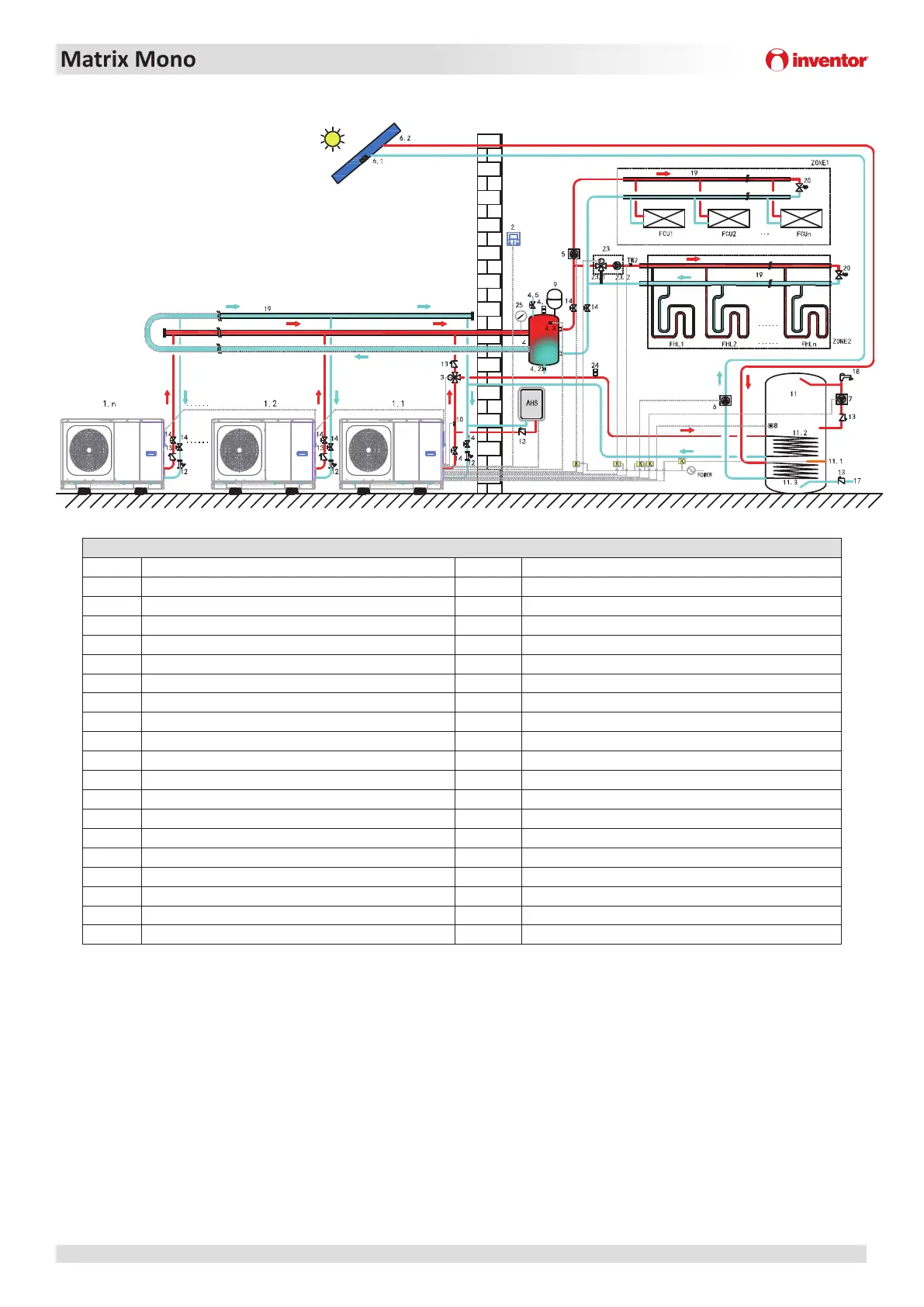
Figure 1-5.5: Applicaon 3- Parallel system control
Legend
1.1 Master unit 11.3 Coil 2: heat exchanger for heat pump
1.2…n Slave unit 12 Filter(Accessory)
2 User interface 13 Check valve (Field supply)
3 SV1: 3-way valve(Field supply) 14 Shut-off valve(Field supply)
4 Balance tank(Field supply) 17 Tap water inlet pipe(Field supply)
4.1 Automac bleed valve 18 Hot water tap(Field supply)
4.2 Drainage valve 19 Collector/Distributor(Field supply)
4.3 Tbt1: Balance tank upper temperature sensor(oponal) 20 Bypass valve(Field supply)
4.5 Filling valve 23 Mixing staon(Field supply)
5 P_O: Outside circulaon pump (Field supply) 23.1 SV3: Mixing valve(Field supply)
6 P_S: Solar pump(Field supply) 23.2 P_C: Zone B circulaon pump(Field supply)
6.1 Tsolar: Solar temperature sensor(Oponal) 24 Automac bleed valve(Field supply)
6.2 Solar panel (Field supply) 25 Water manometer(Field supply)
7 P_D: DHW pipe pump(Field supply) Tw2 Zone B water flow temperature sensor(Oponal)
8 T5: Domesc water tank temperature sensor(Accessory) RAD 1…n Radiator(Field supply)
9 Expansion vessel(Field supply) FHL 1…n Floor heang loop(Field supply)
10 T1: Total water flow temperature sensor(Oponal) K Contactor(Field supply)
11 Domesc water tank(Field supply) ZONE 1 The space operate cooling or heang mode
11.1 TBH: Domesc water tank heater ZONE 2 The space operate heang mode
11.2 Coil 1: heat exchanger for heat pump AHS Auxiliary heat source(Field supply)
Notes:
1. The example is just for applicaon illustraon; please confirm the exact installaon method according to the installaon manual.
Modularity is perfect when an extension of capacity becomes required as the building cooling/heang demand evolves. 6
units can be controlled in group. The group control system can control and view the operaon of the enre system only by
connecng the master to the wire controller. If the DHW funcon is required, the water tank can only be connected to the
master unit water circuit through a three-way valve, and controlled by the master unit. If AHS is needed, it c
an only be
connected to the master waterway and controlled by the master unit. The Tbt1 temperature sensor must be installed in
the parallel system (otherwise unit cannot be started). If the balance tank is too large, Tbt2 needs to be added in order to
improve the control accuracy. Tbt2 is set in the lower part of the balance tank. The water inlet and outlet pipe joints of
each unit of the parallel system should be connected with so c
on
necons and one-way valves must be installed at the
water outlet pipe.
 Loading...