13
Matrix Mono
12
5.2.2 Mode set control
Figure 1-5.3: Applicaon 2- Mode set control
Legend
1 Ou
tdoor unit 17 Shut-off valve (Field supply)
3 User interface 18 Filling valve (Field supply)
5 Balance tank (Field supply) 19 Drainage valve (Field supply)
5.1 Automac bleed valve 23 Collector/distributor (Field supply)
5.2 Drainage valve 24 Bypass valve (Field supply)
6 P_o: Zone A circulaon pump (Field supply) 25 Hydraulic adapter box (Oponal)
7
SV2: 3-way
valve (Field supply) RT 1…7 Low voltage room thermostat (Field supply)
13 Expansion vessel (Field supply) RT8 High voltage room thermostat (Field supply )
15 Filter (Accessory) FHL1…n Floor heang loop (Field supply)
FCU1...n Fan coil unit (Field supply)
Notes:
1. The example is just for applicaon illustraon; please confirm the exact installaon method according to the installaon manual.
Space heang
Cooling or heang mode is set via the room thermostat, water temperature is set on the user interface. 1) When any “CL”
of all the thermostats close, system will be set at cooling mode. 2) When any “HL” of all the thermostats close and all “CL”
open, system will be set at heang mode.
The circulaon pumps operaon
1) When the system is in cooling mode, which means any “CL” of all the thermostats closes, SV2(7) keeps OFF, P_o(6) starts
running;
2) When
the system is in heang mode, which means one or more
“HL” close and all “CL” open, SV2(7) keeps ON, P_o(6)
starts running.
Part 1 - General Informaon
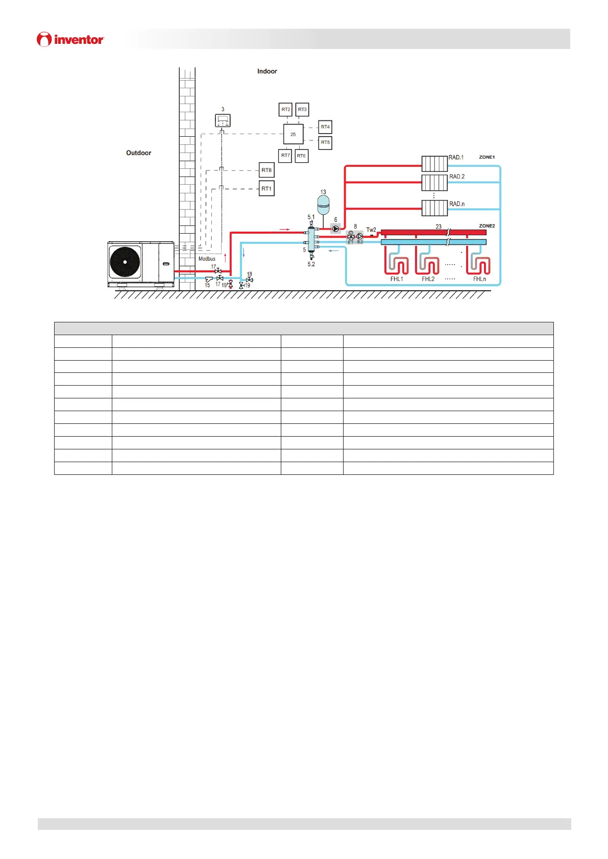
5.2.3 Double zone control
Figure 1-5.4: Applicaon 2-Double zone control
Legend
1 Outdoor unit 17 Shut-off valve (Field supply)
3 User interface 17 Shut-off valve (Field supply)
5 Balance tank (Field supply) 18 Filling valve (Field supply)
5.1 Automac bleed valve 19 Drainage valve (Field supply)
5.2 Drainage valve 23 Collector/distributor (Field supply)
6 P_o: Zone A circulaon pump (Field supply) 25 Hydraulic adapter box (Oponal)
8 Mixing staon (Field supply) RT 1…7 Low voltage room thermostat (Field supply)
8.1 SV3: Mixing valve (Field supply) RT8 High voltage room thermostat (Field supply )
8.2 P_c: zone 2 circulaon FHL1…n Floor heang loop (Field supply)
13 Expansion vessel (Field supply) Tw2 Zone 2 water flow temperature sensor (Oponal)
15 Filter (Accessory) RAD.1...n Radiator (Field supply)
Notes:
1. The example is just for applicaon illustraon; please confirm the exact installaon method according to the installaon manual.
Space h
eang
Zone1 can operate in cooling mode or heang mode, while zone2 can only operate in heang mode; While installaon, for
all thermostats in zone1, only “H、L” terminals need to be connected. For all thermostats in zone2, only “C、L” terminals
need to be connected.
1) The ON/OFF of zone1 is controlled by the room thermostats in zone1. When any “HL” of all thermostats in zone1 closes,
zone1 turns ON. When all “HL” turn OFF, zone1 turns OFF; Target temperatu
re a
nd operaon mode are set on the user
interface;
2)
I
n heang mode, the ON/OFF of zone2 is controlled by the room thermostats in zone2. When any ”CL” of all thermostats
in zone2 closes, zone2 turns ON. When all “CL” open, zone2 turns OFF. Target
temperature is set on the user interface; Zone 2 can only operate in heang mode. When cooling mode is set on the user
interface, zone2 keeps in OFF status.
The circulaon pump operaon
When zone 1 is ON, P_o(6) starts running; When zone 1 is OFF, P_o(6) stops running;
When zone 2 is ON, SV3(8.1) is ON, P_c(8.2) starts running; When zone 2 is OFF, SV3(8.1) is OFF, P_c(8.2) stops running .
The floor heang loops require a lower water temperature in heang mode compared to radiators. To achieve these two
set points, a mixing staon is used to adapt the water temperature according to requirements of the floor heang loops.
The radiators are directly connected to the unit wat
er c
ircuit and the floor heang loops are aer the mixing staon. The
mixing staon is controlled by the unit.
 Loading...