Mod. TI-14
Adjustment Instructions
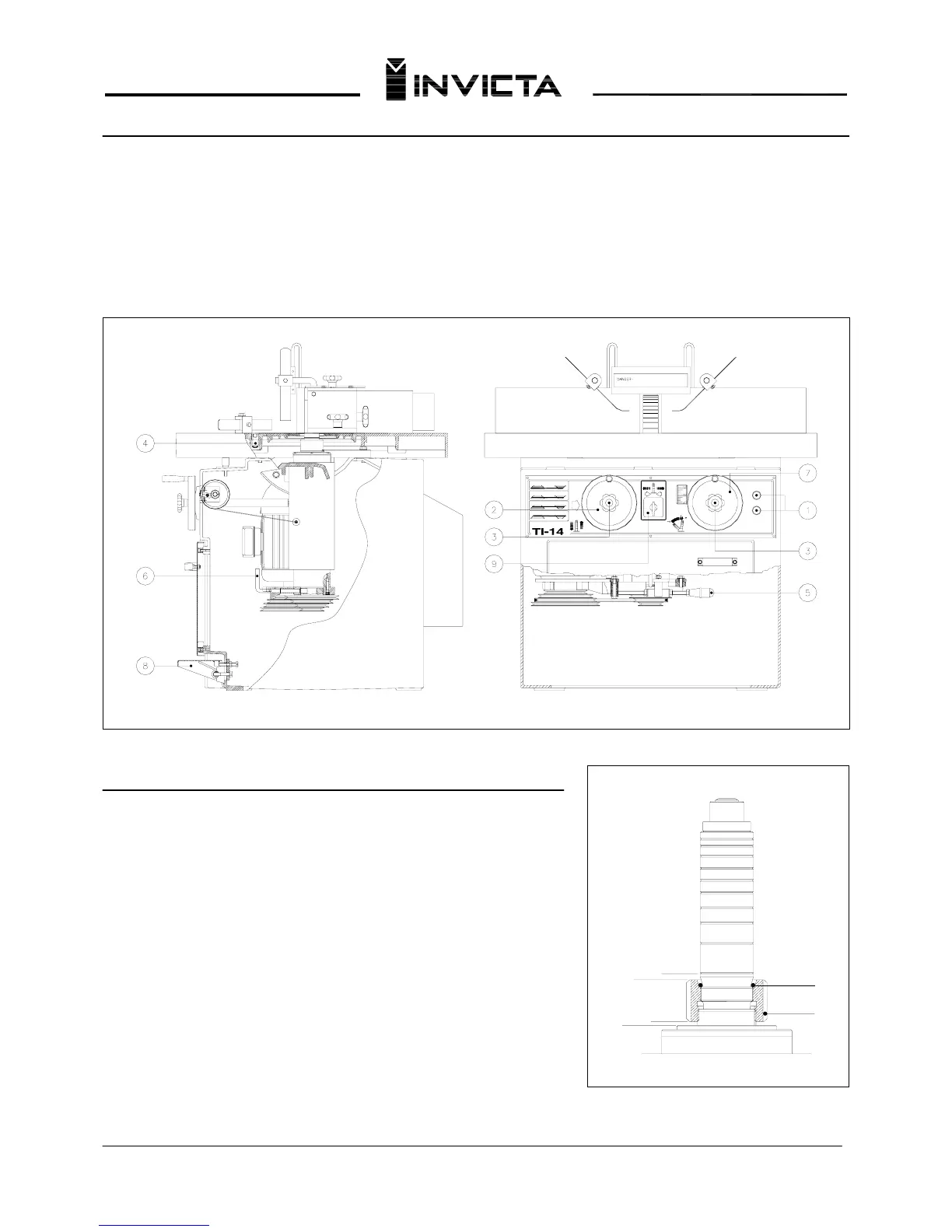
Controls
1 – On (Green) and Off (Red) Switches 6 – Spindle lock lever
2 - Vertical Height Adjusting Handwheel 7 - Tilt Adjustment Handwheel (Ver. 3 and 5)
3 – Handwheel Lock 8 – Brake
4 – Sliding Table Lock (Ver. 4 and 5) 9 – Spindle Reversing Switch
5 - Belt tension lever
C
D
F
E
A
B
Inserting the Interchangeable Spindles (Cutter Shafts)
Fig. 3
Turn Lever nº 6 to its horizontal position locking the drive shaft.
Loosen knob nº 3 and turn handwheel nº 2 until the shaft reaches its
maximum height. Screw nut “A” onto the interchangeable spindle shaft
to be used until tightening up against rubber ring “B”. Then screw this
assembly into the drive shaft turning the nut until the assembly is
securely tightened. Finally unlock the drive shaft by lever nº 6.
IMPORTANT:
1. When assembling the nut to the spindle, face “C” should be slightly
higher than face “D”.
2. When changing spindles, the locknut face “E” should never come
in contact with surface “F”. If this occurs, change the relation of the
locknut to the shaft before tightening.
3. Never allow debris to come between shaft and the spindle housing.
4. Protect the spindle mating surfaces from damage at all times.
Fig. 4
06