Chapter 2. Installation of outdoor unit
10 Shenzhen INVT Network Technology Co., Ltd.
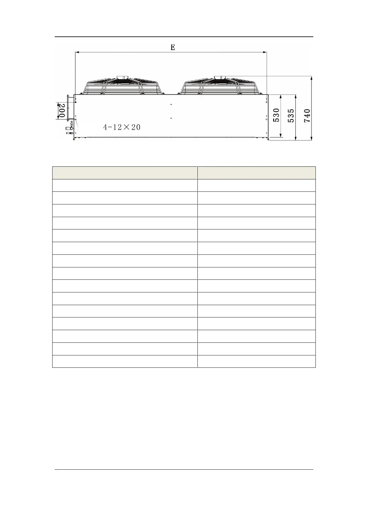
Figure 2-2 Dimensional drawing of horizontal mounting base (bottom view)
Table 2-2 Horizontal mounting base/mounting hole dimensions (unit: mm)
Note
The mounting holes are waist-shaped holes, and bolts need to be used to fix the mounting
base.
2.2.2.3 Low temperature component mounting base
The dimensions of the low temperature component mounting base and parts are shown in
Figure 2-3, where the specific dimensions of each model are shown in Table 2-3.

 Loading...