Chapter 2. Installation of outdoor unit
Shenzhen INVT Network Technology Co., Ltd. 13
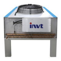
Figure 2-7 Low temperature component installation diagram
2.2.4 Fixation
After the installation location and installation method of outdoor unit is determined, carry the
outdoor unit to the installation location and fix it with M10×30 screws or expansion screws. The
installation should be firm, and stainless steel screws are recommended.
2.2.5 Indoor and outdoor unit piping connection
Please refer to the relevant mechanical installation guidelines in the indoor unit user manual.
2.2.6 Indoor and outdoor unit cable connection
2.2.6.1 Determine the cable specification
Select the power supply cable and signal cable specifications according to the rated operating
current of the fan (see Table 2-1) and installation distance and other site factors.
Table 2-1 Recommended cable diameter for outdoor unit
Recommended
Power Cable
Specifications
(mm
2
)
Recommended
Signal Cable
Specifications
(mm
2
)
VCP026SF/VCP028SF/
VCP034SF/VCP038SF
VCP045SF/VCP056SF/VCP056DF
VCP066SF/VCP076SF/VCP088SF/
VCP096SF/ VCP066DF/VCP076DF
VCP088DF/VCP096DF
Note
The outdoor portion of the cable connecting the indoor unit to the outdoor unit requires the
use of a protective tube.
 Loading...