27
EN
8. SANITIZING
Necessary materials:
• Manual valve.
• Measuring cup with connectors.
• Sanitizing cleaner of water treatment equipment.
• Disposable vinyl gloves.
• Strips to detect hydrogen peroxide.
• Sanitizing spray.
• Paper napkin.
Sanitize the equipment when necessary during initial
operation, (whenever there is a risk of contaminating
the appliance due to the manipulation of components in
contact with water) or within the indicated frequency.
To do so, follow the instructions below:
WARNING: Water used during the sanitizing pro-
cess must be drinking water from the public ne-
twork and comply with the corresponding drinking
quality requirements from RD 140/2003, EU Directive
98/83 or the local regulations in force.
• Keep the inlet valve closed (1) and relieve the pressure
of the tank by dispensing some water.
• Use disposable vinyl gloves to handle sanitizing pro-
ducts.
• Place the dosage housing in between the equipment's
inlet tube. On this purpose:
• Disconnect the inlet tube of the system marked as
“Water Inlet” and place the dosage housing between
the water inlet and the inlet of the appliance (2).
For an easier and more comfortable access during the
sanitizing process and the opening and closing of the
inlet valve, if the water inlet valve is inaccessible or too
far from the equipment, a manual valve in the closed
position can be placed along with the sanitizing dosage
housing. This valve will work as the manual inlet valve of
the system.
• Once the set has been installed, keep the new inlet
valve closed and open the inlet valve (3). The dosage
housing must be initially empty.
• Pour 50 ml of sanitizing product in the dosage housing
placed at the appliance's inlet (4). Screw the housing
properly in its head.
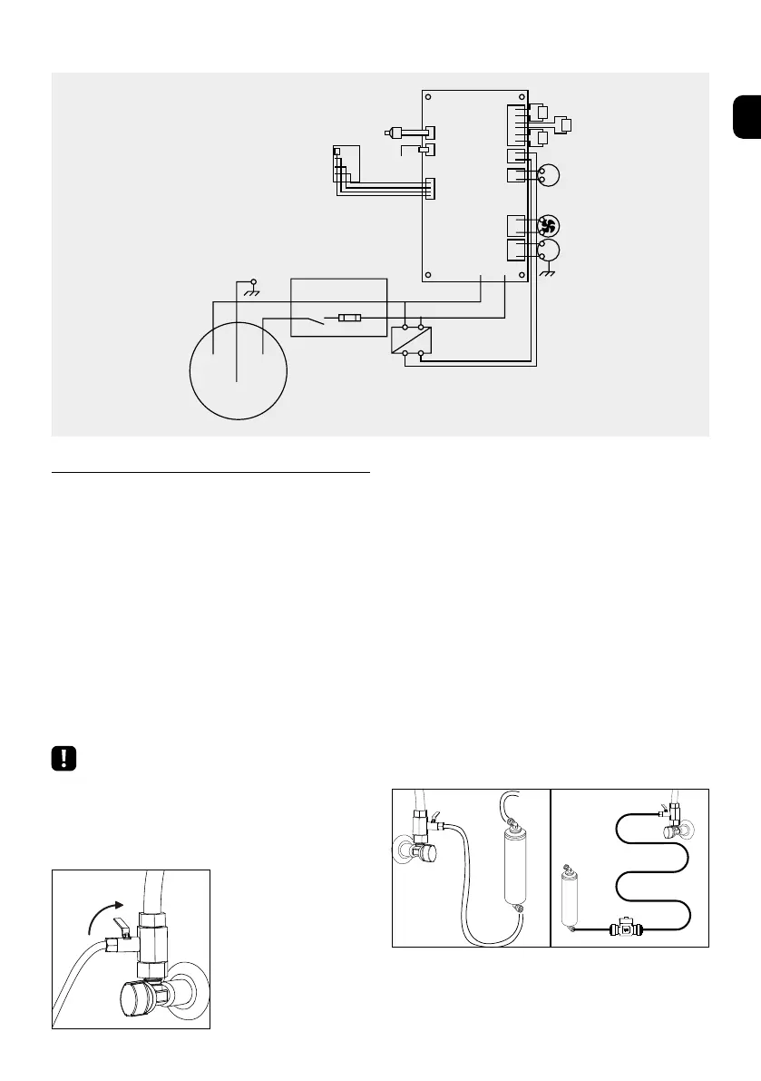
ESQUEMA ELÉCTRICO
1
Close
32
Close
Close
Open
Open
Open
COMPRESSOR
TRANSFORMER
FUSE
DISPLAY
SWITCH
POWER SUPPLY
220/240V/50HZ
FAN
PUMP
TEMPERATURE
SENSOR
LEVEL
PROBE
ROOM EV
GAS EV
COLD EV