Ficha técnica
*
For salinity higher than 1500ppm consult your dis-
tributor.
** Higher hardnesses may shorten the life and func-
tion of certain components.
*** Maximum accumulation as a function of inlet
pressure.
**** Flow rates may vary by 20% depending on the
temperature, pressure and specific composition of
the water to be treated.
***** May vary depending on model.
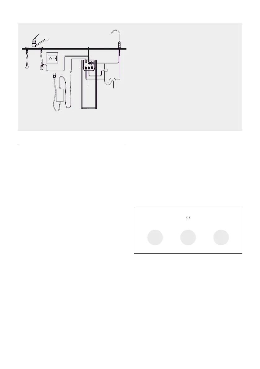
HYDRAULIC WIRING DIAGRAM
2. OPERATION OF THE EQUIPMENT
- The mains water to be treated enters the equipment
through the pre-filtration stage which features a GAC
(CF) turbidity and carbon filter. In this filtration stage,
suspended particles, chlorine, its derivatives and other
organic substances are retained.
- The unit features a minimum pressure switch to pro-
tect the pump against pressure drops in the network
(LPS).
- The flow of water into the equipment is controlled by
a solenoid shut-off valve (Si).
- The water, after being treated in the filtration stage,
is pushed towards the reverse osmosis (RO) membrane.
The equipment incorporates a pump (P) to increase the
pressure. The pressure of the water on the membrane
makes the reverse osmosis process possible.
- Before going out through the tap, the water passes
through the post-charcoal filter, which improves the
taste.
- Rejected water or water containing excess salts and
other dissolved substances is directed to the drain for
disposal.
- The direct flow equipment controls the start and stop
by means of a pressure switch (HPS).
- The equipment incorporates different functional and/
or security systems, managed by a state-of-the-art
electronic module:
- Electronic leak detection system (L). When the system
detects this situation, it blocks the equipment emitting
an acoustic and luminous signal informing about it. The
equipment will remain blocked until the detection pro-
be is dry.
- Probe for estimating the conductivity of the water
produced to evaluate the condition of the membrane
and components (Q). When water is dispensed through
the tap, the system will measure the conductivity of the
water produced.
- Automatic filter change warning, in order to inform
the user that proper maintenance must be carried out
to guarantee the quality of the water dispensed.
3. INTERFACE. STATE OF THE SYSTEM
Display
3.1 WATER QUALITY INDICATOR COLORS
- Blue: TDS≤100ppm
- Lilac: 100ppm < TDS ≤ 150ppm
- Red: TDS > 150ppm
CF RO CB
Indicador de calidad del agua o fallo
Indicadores / pulsadores de vida de los filtros
1. Interfaz de datos
2. Desagüe
3. Grifo
4. Entrada
5. “Power”
1
2
3
4 5
 Loading...