AVXP1 Owner Manual 6
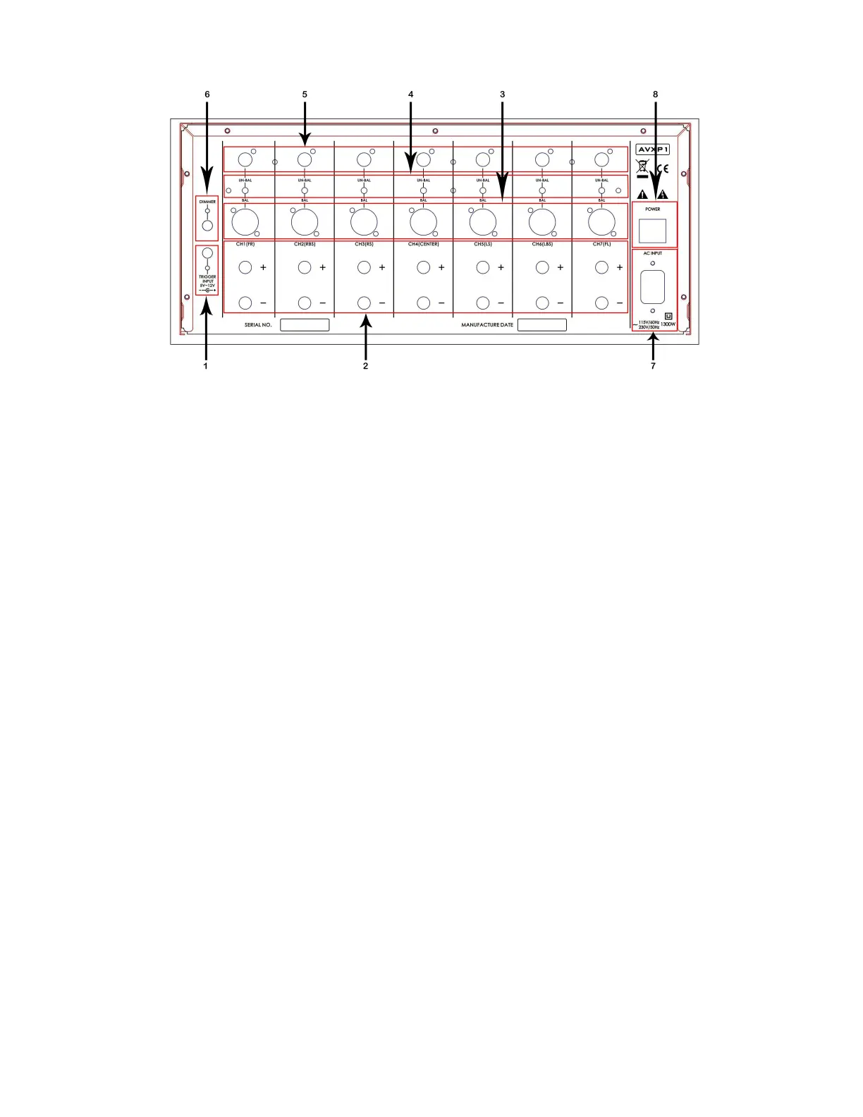
Back Panel
1. TRIGGER INPUT PORT
This input gets a 12V signal from a connected device such as AV1 or AVX1 to power ON AVXP1.
2. 7 CH OUT (multichannel) SPEAKER OUTPUT
Front L/R, Centre C, Surround L/R, Back Surround L/R. All these multi-channel, audio output ports
connect the speakers to the system. The correct polarity should be followed (+) and (–) as
indicated in the unit. In principle, speakers will show (+) with a RED indication and (–) with a
BLACK indication.
3. 7.1CH IN (multichannel) BALANCED INPUT
Front L/R, Centre C, Surround L/R, Back Surround L/R. All these multi-channel, balanced, audio
input ports can connect to the analogue, balanced, audio output ports of the multi-channel
Audio Video Processor AV1 or AVX1.
4. AUDIO INPUT MODE SELECTION SWITCH
Depending on the type of connection selected to connect AVXP1 to the Audio Video Processor
AV1 or AVX1, these switches should be positioned accordingly. Position the switch into UN-BAL
for UNBALANCED connection or on BAL for BALANCED connection.
5. 7.1CH IN (multi-channel) UNBALANCED INPUT
Front L/R, Centre C, Surround LS/RS, Back Surround LNS/RBS. All these multi-channel, audio input
ports can connect to the analogue, audio output ports of the multichannel Audio Video
Processor AV1 or AVX1.