IOXUS, INC.
18 Stadium Circle
Oneonta, NY 13820
Toll Free: +1 877-751-4222 Fax: 607-433-9014 http://www.ioxus.com sales@ioxus.com 2/21/2019
DOC 1-0004 Rev A
© 2017 Ioxus, Inc. All rights reserved. 4
Installation
Maintenance Mode
WARNING!CONNECTIONOFuSTART®TOANENERGYSOURCEWHENLIVEVOLTAGEISPRESENT
ONuSTART®TERMINALSCOULDCAUSEPERSONALINJURYOREQUIPMENTDAMAGE!
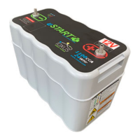
uSTART
®
will be shipped in Maintenance Mode. The solid yellow LED will light while uSTART
®
is first
connected to a battery to show it is in Maintenance Mode. uSTART
®
is now ready to support the vehicle
and will automatically enter Run Mode when the vehicle starts.
Mounting Location
uSTART
®
is designed to mount in the same space as a group 31 battery. The typical installation location is in
the battery box of a Class 3 – 6 truck. uSTART
®
must be installed in parallel with at least one battery in
order to function and provide energy. If there are two or more batteries in a battery box, one can be
removed to make room for uSTART
®
.
On some truck models the Diesel Particulate Filter After-Treatment System or other exhaust components
may be located near the battery box. These systems can generate very high temperatures during operation
which may cause uSTART
®
to exceed +149°F (+65°C). If the vehicle battery box is near the Diesel Particulate
Filter After-Treatment System or any part of the exhaust, mount uSTART
®
in a location far away from it or
install heat shielding capable of preventing uSTART
®
from experiencing +149°F (+65°C) temperatures under
worst case conditions.
Pre-Installation Checks
1. Test the vehicle starting and charging system prior to installing uSTART
®
to isolate any pre-existing
problems. Refer to Recommended Practice 129A (RP 129A) of the American Trucking Association
(ATA) Technology and Maintenance Council (TMC) for procedures to test cable connections between
all starting and charging system components for maximum voltage drop. Repair any issues found
before proceeding.
2. Remove the cables from the negative (-) terminal(s) of the vehicle battery(s).
3. Remove the cables from the positive (+) terminal(s) of the vehicle battery(s).
4. All cable terminations and battery terminals should be cleaned thoroughly to remove all oxidation and
grease.
5. Test the vehicle battery(s) individually to ensure that they are properly charged. Remove and replace
any batteries that are discharged below their specified voltage or failed to meet their CCA rating.
6. If there is no additional space in a vehicle’s battery box, remove a battery to make room for
uSTART
®
.
7. Place uSTART
®
in the desired mounting location.
8. Check that uSTART
®
positive (+) and negative (-) terminals line up with positive (+) and negative (-)
terminals on remaining battery(s) and vehicle positive (+) and negative (-) battery cables.
 Loading...