36/40
GPIO pin define please refer to the part of Front / Back plane & I/O
port pin assignment
GPIO 0
GPIO 1
ALARM INPUT
Normal: 3.3V (The voltage differential from GPIO pin & GND)
Active: 0V (GPIO 0 & GPIO1 link to PIN2 GND)
GPIO 2
GPIO 3
ALARM OUTPUT
Normal: 3.3V (The voltage differential from GPIO pin & GND)
Active: 0V (GPIO 0 & GPIO1 link to PIN2 GND)
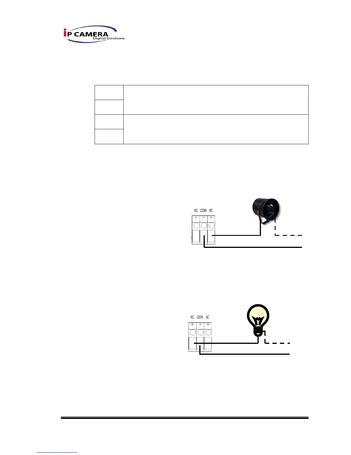
GPIO INSTALLATION EXAMPLE 1
Trigger a normal off (Normal Open) alarm siren on when event/motion
occur at COM:
GPIO INSTALLATION EXAMPLE 2
Trigger the normal on (Normal Close) indoor illumination off when event
/ motion occur at COM:
9PIN D-SUB
WEB SERVER / IP CAMERA
9PIN D-SUB
WEB SERVER / IP CAMERA