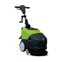
5.7. Lifting and transporting the machine
IMPORTANT
All phases must be performed in an adequately lit room and adopting the safety
measures most appropriate to the situation.
The operator must always use personal protection devices.
To load the machine onto a means of transport, proceed as follows:
• empty the dirty water and detergent tanks;
• place the machine in the packaging, then rest the packaging on a pallet and fix it with
plastic straps;
• lift the pallet (with the machine) using a fork lift truck and load it onto the means of
transport;
• anchor the machine to the means of transport with cables connected to the pallet and
machine itself.
6. PRACTICAL GUIDE FOR THE OPERATOR
6.1. Controls - Description
With reference to fig. C, the machine has the following controls and indicator lights:
• Power on light (fig. C, ref. 7 - cable model only): green, indicates that the machine's
power cable is connected to the mains.
• Battery charge light (fig. C, ref. 2 - battery models only): 3 LEDs (red, yellow and
green) which indicate the level of battery charge. There may be:
a) red, yellow and green LEDs on: battery voltage >24V;
b) red and yellow LEDs on: battery voltage <24V;
c) red LEDs on: battery voltage <23V;
d) red LED flashing: battery voltage <21.5V, batteries completely flat; after a few
seconds the brush and suction motor shut down;
• Main Switch (fig. C, ref. 3): enables and disables electrical power to all machine
functions (to turn the machine off, hold the button down for at least 4 seconds).
• Brush button with light (fig. C, ref. 4): enables (LED on) and disables (LED off) the
"brush" function. The brush does not start rotating until the brush lever is operated.
• Suction button with light (fig. C, ref. 5): turns the suction motor on (LED on) and off
(LED off) to dry the floor being washed. The light is on when there is power to the
suction motor.
• Detergent button (fig. C, ref. 6): enables (LED on) and disables (LED off) detergent
flow. The detergent does not flow unless the brush is rotating.
• Brush lever (fig. D, ref. 1): enables brush rotation.
• Squeegee lever (fig. D, ref. 2): raises (if lowered) or lowers (if raised) the squeegee.
• Handle regulation lever (fig. D, ref. 3): allows the angle of the handle to be adjusted.
6.2. Mounting and adjusting the squeegee
The squeegee (fig. A, ref. 5) is responsible for the first phase of drying.
To mount the squeegee on the machine, proceed as follows:
1) check that the squeegee mount (fig. E, ref. 1) is lowered, otherwise lower it by means
of the squeegee lever (fig. D, ref. 2);
2) rotate the machine backwards and rest the handle on the floor;
3) insert the two threaded pins on the squeegee into the slots on the support (fig. E, ref.
1);
4) fix the squeegee by tightening the two knobs (fig. E, ref. 2);