EasyManua.ls Logo

iPECS eMG100 - Modular Jack Wiring for Basic Extension for KSU-D

iPECS eMG100
101 pages
Print Icon
To Next Page IconTo Next Page
To Previous Page IconTo Previous Page
Loading...
iPECS eMG100
Hardware Description and Installation Manual Issue 1.1
64
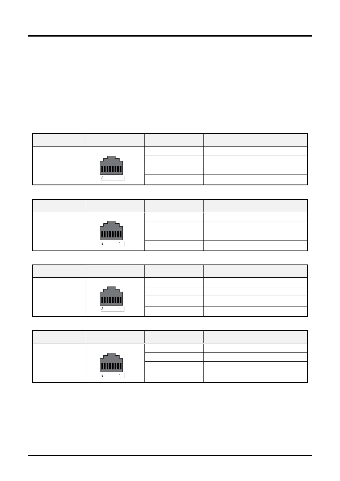
6.4.2.1 Modular Jack Wiring for Basic extension for KSU-D
KSU-D provides both a Digital and SLT port. These Station modular jacks are terminated with one Digital and
one SLT circuit to an RJ45 jack as shown in the chart below.
To wire the SLT and Digital Station modular jacks,
1) Wire each SLT Station modular jack to the termination point.
2) Wire each Digital Station modular jack to the termination point.
3) Tag the wiring for future maintenance.
Table 6.4.2.1 SLT and Digital Station Modular Jack Wiring for KSU-D
Connector
Pin-out
Pin Number
Signal Name
RJ45 (MJ2-1)
4,5
DKT1-T, DKT1-R
7,8
DKT3-T, DKT3-R
1,2
DKT5-T, DKT5-R
3,6
N.C
Connector
Pin-out
Pin Number
Signal Name
RJ45 (MJ2-2)
4,5
DKT2-T, DKT2-R
7,8
DKT4-T, DKT4-R
1,2
DKT6-T, DKT6-R
3,6
N.C
Connector
Pin-out
Pin Number
Signal Name
RJ45 (MJ2-3)
4,5
SLT1-T, SLT1-R
7,8
DKT7-T, DKT7-R
1,2
DKT8-T, DKT8-R
3,6
SLT3-T, SLT3-R
Connector
Pin-out
Pin Number
Signal Name
RJ45 (MJ2-4)
4,5
SLT2-T, SLT2-R
7,8
N.C
1,2
N.C
3,6
SLT4-T, SLT4-R

Table of Contents