WARNING
Exposure to radio frequency energy (RF) from the antenna may cause thermal injuries including
tissue damage from increased heating and body temperature. Keep everyone at a safe distance from
the antenna when the system power is ON. Personnel must maintain a minimum separation distance
of 1.0 m (3.3 ft.) from the unit and installers must place ODU transmitter in a manner to maintain
minimum spacing requirement. Failure to do so could result in exposure to radio frequency energy
(RF) transmitted from the ODU that could result in serious injury or death.
R
a
d
i
a
t
i
o
n
H
a
z
a
r
d
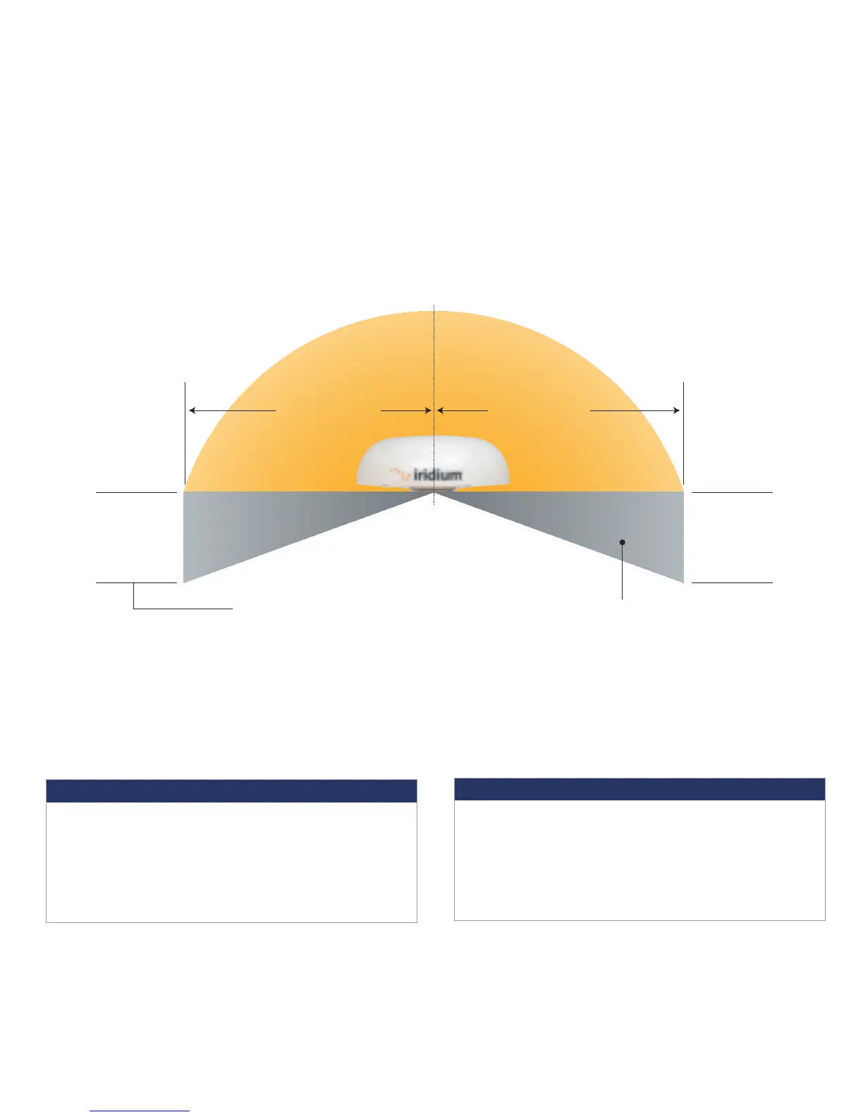
1.0 m (3.3 ft.)
Unobstructed view of sky all directions
Unrestricted area for obstructions
8.0 m (26.2 ft.)
2.0 m (6.6 ft.)
8.0 m (26.2 ft.)
No metallic or concrete
obstructions in
grey shaded area
Minimize
obstructions
Minimize
obstructions
S-band (-10 cm/ 3 GHz) radars
Radar Power Min distance at 15˚ Min distance at 60˚
vertical separation vertical separation
0-10kW 0.4 m (1.3 ft.) 0.4 m (1.3 ft.)
30kW 1.0 m (3.3 ft.) 0.5 m (1.6 ft.)
50kW 2.0 m (6.6 ft.) 1.0 m (3.3 ft.)
X-band (~3 cm/ 1 GHz) and C-band (4-8 GHz) radars
Radar Power Min distance at 15˚ Min distance at 60˚
vertical separation vertical separation
0-10kW 0.8 m (2.6 ft.) 0.4 m (1.3 ft.)
30kW 2.4 m (7.9 ft.) 1.2 m (3.9 ft.)
50kW 4.0 m (13.1 ft.) 2.0 m (6.6 ft.)
Minimum distance from S-band & X-band RADARs
Offset Distances from other Communications &
Navigation Equipment ODU Location Priorities
Keep clear of sources of interference, such as RADAR systems, high power transmitters,
or other satellite communication terminals.
Place the ODU transmitter in a manner to maintain the minimum spacing requirement of 1.0 m
(3.3ft) from the antenna to personnel. This distance is in effect within 0 - 180 degrees of the
antenna elevation range.
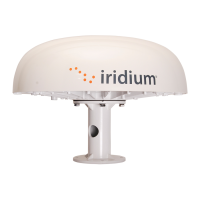
STEP 1: LOCATION FOR ODU
Conduct a visual survey to determine the best location for the ODU. The ODU
needs clear exposure, in all directions, to the sky to avoid interference.
Prior to final installation, temporarily connect the system and use the built in Site Survey Tool to validate
the installation location. (See the Installation Guide). Use the ODU box to temporarily support the ODU if
needed. Orient the ground lug on the ODU to face "aft" at the install location. Connect the ground cable
temporarily to the system and local ground connection. Before connecting the ODU/IDU cable, use the
electrical clips to ground the RJ-45 connector to ground to prevent static discharge. Connect the ODU/IDU
cable to the ODU and then remove the electrical clips and connect the cable to the IDU. Connect the
system to nearby available power and use the Site Surrey Tool to validate the installation location.
RF Label on top of ODU
W
A
R
N
I
N
G
A
D
V
E
R
T
E
N
C
I
A
A
V
E
R
T
I
S
S
E
M
E
N
T
!
!
!
STAY BACK ONE
METER (3.3FT)!
Failure to do so
could result
in radio
frequency
(RF) energy
exposure causing thermal
injuries, serious injury
or death.
87804_TPQSG1301.indd 4 1/30/14 2:28 PM
 Loading...