STEP 4: THE ODU/IDU CABLE
Once the ODU site is known, a IDU location must be selected that is within 10 or 30 meters, account-
ing for the path through the cable chase. Remove the electrical clips from the RJ-45 connector from
Step 3. Drill the necessary hole to route the cable to the IDU mounting location. The RJ-45 connector
is smaller than the ODU connector so use a pull string attached to the cable jacket (not the connec-
tor) to pull the cable. Cover the RJ-45 with electrical tape to protect it during the pull. Leave just
enough service loop at the ODU and store any excess cable in the cable chase or near the IDU.
Connect the ground cable to the ODU and to the ground location at the installation site. Use the
adapter kit if you need to change the length of the ground cable.
STEP 5: INSTALL THE IDU
The Indoor Unit (IDU) should be located within 10m or 30m of the ODU, depending on the cable
ordered with the kit. The IDU mounting location should be sheltered from the elements. The IDU should
be mounted on a vertical surface (wall) with cable connectors pointing downward. The wall must be
able to support the weight (1.35 kg, 3 lbs) and have adequate space for the unit that is 250 mm (9.8 in.)
x 190 mm (7.5 in.) x 55 mm (2.16 in.).
1. Layout the locations for the mounting screws, 3 total. The IDU is mounted with the connector edge
facing down.
Note: Use the template in the appendix of the Pilot Installation Guide as a guide for correctly drilling the
mounting holes.
2. Drill and tap holes for M4 flange style mounting screws.
Note: Alternative screws or screw / washer combination may be used. Flange must t into a 4.5 mm
(.18 in.) hole.
3. Hold and screw the IDU against the wall.
4. Remove the SIM cover (retain).
5. Switch the ON/OFF switch in to the OFF position.
6. Remove installation cover from bottom left hand corner of IDU (retain cover and screw).
7. Connect internal cables:
• Remove ground bolt, connect ground cable and replace the bolt to secure the ground
connection (15 in-lbs recommended torque).
• Connect the other end of the ground wire to a local ground connection (not an electrical
system ground) using appropriate clamp or connection.
• Fit power feed from the DC buss or from the supplied PSU to power connector on IDU,
use strain relief provided within IDU.
• Connect RJ-45 connector from ODU/IDU cable to the IDU and use strain relief provided within IDU.
8. After checking that all the connections are securely made and have strain relief, replace and fasten
the installation cover.
Note: For direct connection to DC mains power, see the Installation Guide for installation details.
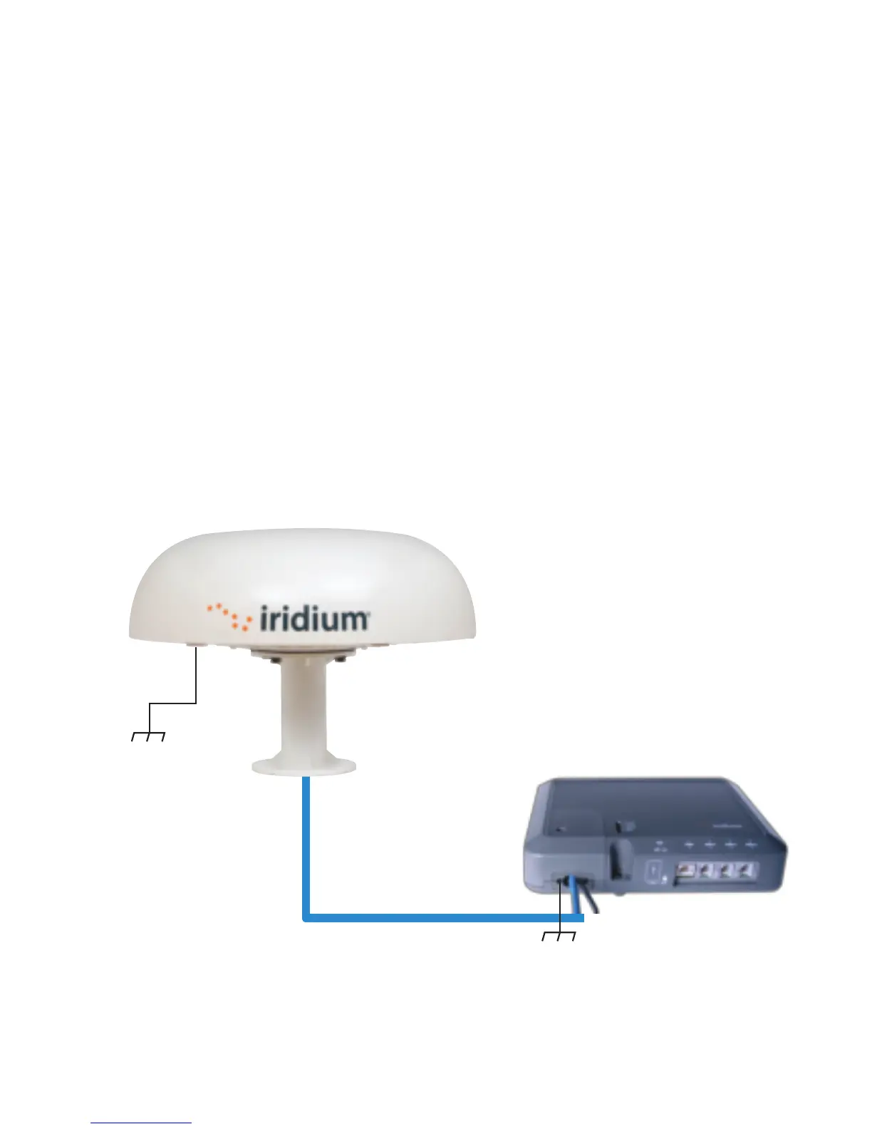
Outdoor Unit
Indoor Unit
Interconnect Cable
10 m (optional 30 m)
WARNING
The Indoor Unit (IDU) contains low voltage that may cause serious injury if opened. Do not, under
any conditions, open or dismantle the IDU. Failure to follow these instructions could result in
serious injury or death.
Shock Hazard
Ground Cable
3 m (8 m available)
IDU Ground Cable 2.5 m
87804_TPQSG1301.indd 8 1/30/14 2:28 PM
 Loading...