INSTRUCTION MANUAL
INDOOR DUAL PROGRAM CONTROLLER
WITH MASTER VALVE/PUMP START & WATER BUDGETING
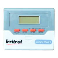
Junior Plus 2/4/6/8
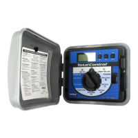
Remove the lower cover. Place the unit on the wall using one slot and one fixed
hole inside the battery slot. Connect the solenoid wires to the terminal block.
One wire from each solenoid should be connected to "C"-Common. The other wire
from each solenoid connects to its respective number on the terminal block.
Connect the transformer wires to the terminal block marked 24VAC.
Only after all your wiring is done and checked, connect the 2 x 1.5 volt AA
alkaline batteries. The display will now be on. Plug the transformer into the
power outlet.
IMPORTANT INFORMATION
•
The NEXT STEP button leads you through the programming steps.
•
Auto Return: If within 3 minutes you do not touch any button, the controller will
automatically return to AUTO mode except from MANUAL mode.
•
Quick Digit Advance: If you press ON/+ or OFF/- continuously, the digits will
advance quickly.
•
Reset Display Back To OFF: In WATERING TIME or START TIME positions.
If you press ON/+ and OFF/- simultaneously and hold for a few seconds, the digits
displayed will reset back to OFF.
•
Program Erase: In AUTO RUN mode, press ON/+ and OFF/- simultaneously until
arrow starts to flash. It will flash 5 times to complete Program Erase.
•
Start Time Stacking: In case of overlap of two or more start times, the controller
will automatically delay the start time until the previous cycle is completed.
BATTERY REPLACEMENT
Replace the 2 x 1.5 volt AA alkaline batteries once a year. Unplug the transformer
before replacing the batteries. Plug in the transformer only after the new batteries are
in place. Replacing the batteries will require reprogramming the controller if the
batteries are not replaced within 15 seconds (before the display fades away).
POWER FAILURE INDICATION
•
If a command to open a zone is initiated during power failure, the "24V" on display
will start flashing.
•
The flashing will stop when the next command to turn on any station is initiated
while power is on.
•
If the fuse is blown, "24V" will also flash. Replace it with a 0.5 amp. fuse.
SOLENOID RATING
The solenoid valve should be rated: 24VAC, 0.35 Amps inrush max. Only 1 solenoid
valve can be connected to each station.
4
Irritrol Systems USA
1-909-785-3623 TELEPHONE
1-909-359-1870 FAX
Irritrol Systems Europe s.p.a.
00-39-765-455201 TELEPHONE
00-39-765-455386 FAX
1
INSTALLATION INSTRUCTIONS