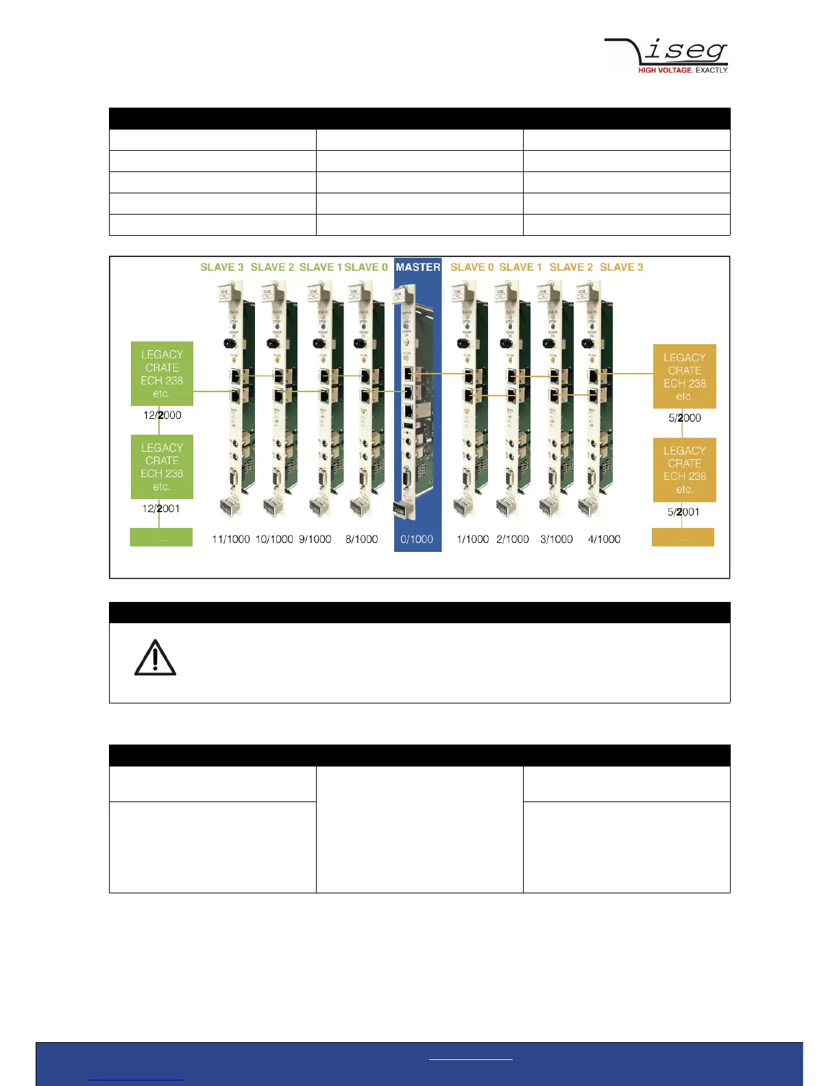
LINE-ID DEVICE-ADDRESS
Yellow line IDs 1-5
Green line IDs 8-12
Controller 2x series 1000
Controller legacy crate series 2000 ...
Modules 0-999
ATTENTION
Before insertion or removal of crate controller, please make sure, all voltages are ramped down, crates
are switched off and power cord is disconnected.
CAN connector LEDs
CC24 (master) CC23 (slave)
Slave is not connected to master or
previous slave
CAN connector indicates line (yellow or
green LED at the connector)
All LEDs are off
Slave is connected to master or previous
slave
CAN LED indicates the color of the
master line, the slave is connected to
The number LEDs indicate the slave´s
order number (note: not the address –
see topology)
Connection and Termination
Both CAN connectors are internally terminated by a 120 Ohm resistor. If two CC2x controllers are directly connected by a direct
assigned (no crossover) FTP Cat. 6 patch cable, no further termination is needed.
Crate Controller CC24/CC23 | v1.4 Last change on: 07.04.2017 | www.iseg-hv.com 7/28
Illustration 1: Topology of CC24/23 series