Óä
isel Ê«>VÌʵիiÌÊ*
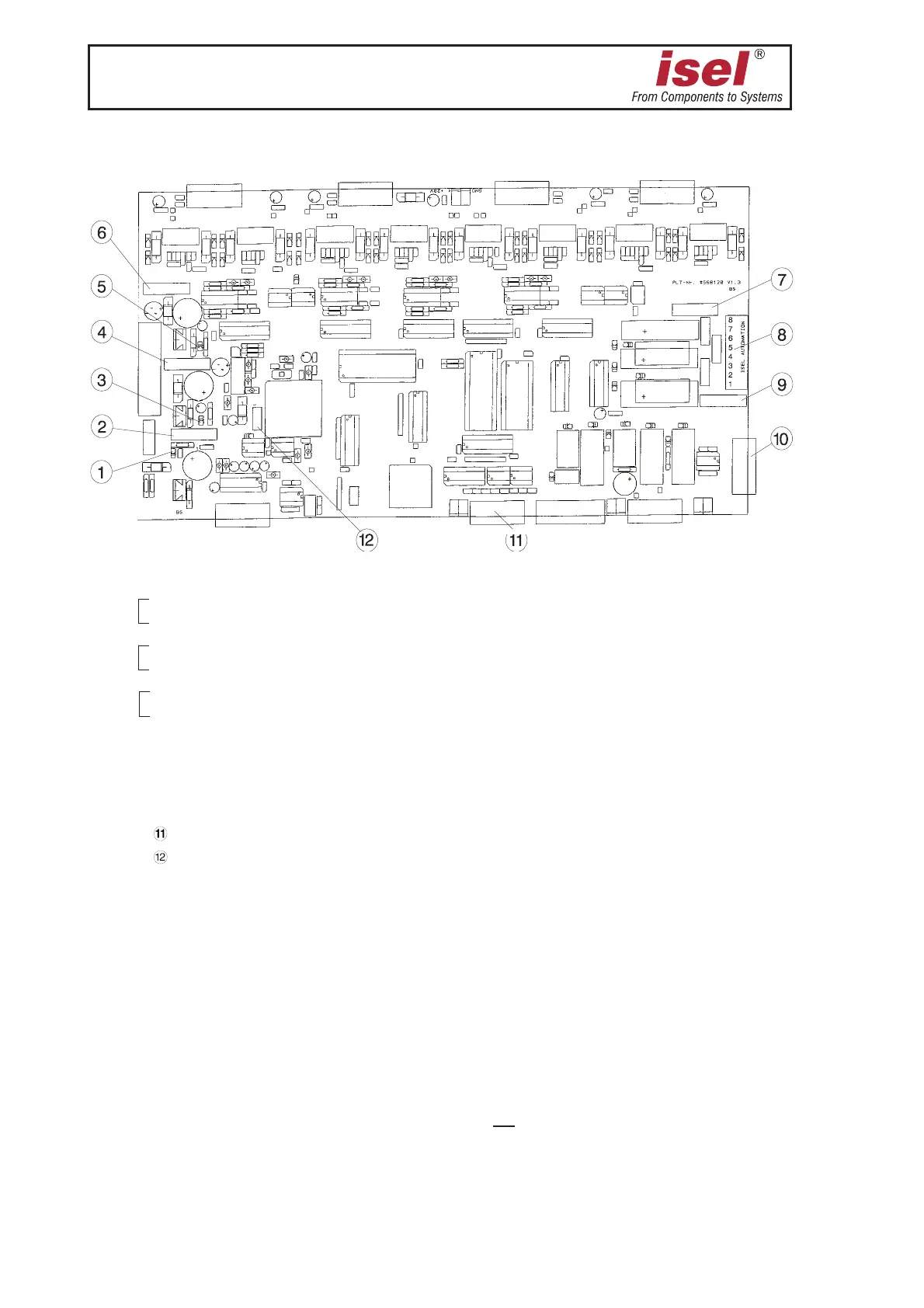
Please refer to the following drawing for the positions of fuses (➁, ➃, ➅, ➆, ➈) and LED’s
(
➀, ➂, ➄).
ÌÀiÀÊ«ÀÌi`ÊVÀVÕÌÊL>À`ÊLi`ÊÌiÊÀi>À«>i
➀ Controller LED Processor supply voltage 10 V/5 V
➁ Input fuse 1,25 Amp, slow ones
➂ Controller LED 24 V I/O voltage
➃ Input fuse 1,25 Amp, slow-blow
➄ Controller LED 24 V safety circuit voltage
➅ Input fuse 1,25 Amp, slow-blow
➆ Supplementary output fuse 230 V, 1,25 Amp, slow-blow HBD
➇ Supplementary output connector 230 V
➈ Tooling machine fuse 230 V, 5 Amp, slow-blow HBD
➉ suppl. outp. 9-pin Sub-D f. con. 15 mA max.
suppl. inp. 9-pin Sub-D fem. con.
H1 jumper field
For special cases (if a switch is defective or in case of power failure etc.), you can manually
open the hood interlock using the triangular wrench.
£° Switch off the machine.
Ó° Remove the four screws of the sheet metal lid of the chassis, then remove the lid.
ΰ Insert the triangular wrench into the interlock from the back and turn it around half a turn
to the left without applying excessive force.
9ÕÊ>ÞÊÌÊ«iÀ>ÌiÊÌiÊ>ViÊÊÌÃÊÃÌ>Ìi°
The tooling machine remains de-energized.