ÓÓ
isel Ê«>VÌʵիiÌÊ*
iÝÌiÀ ÊÊÊÌiÀ
2
3
4
5
6
7
8
9
1
2
3
4
5
6
7
8
9
Ç°Ó *Ê>ÃÃ}iÌ
7.2.1 For the ICP with electronik
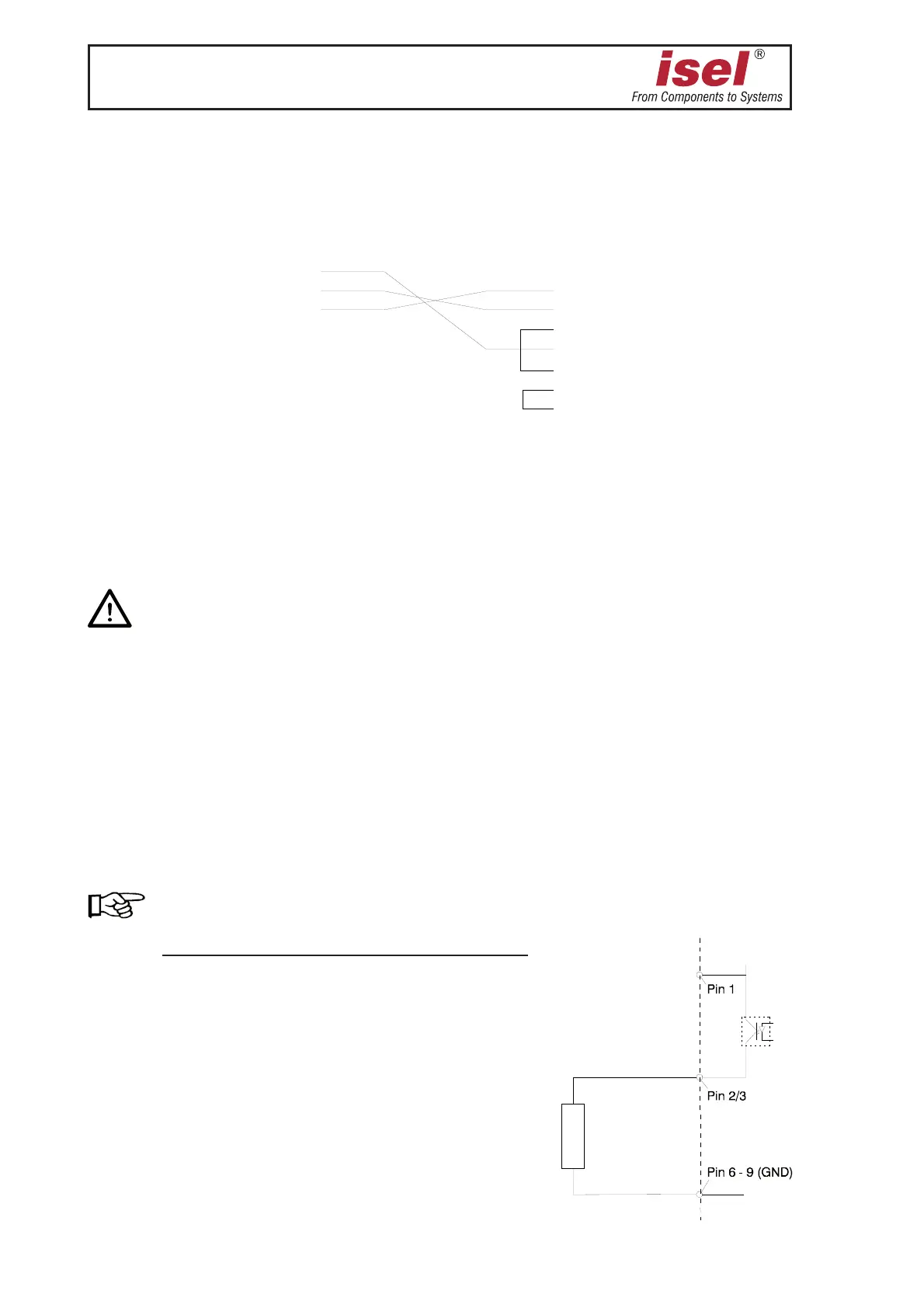
The pin assignment of the connection cable for the serial interface:
Please, consider the following notes if you want to custom-specifically setup the optional
supplementary inputs/outputs:
iÌÊÞÊëiV>ÃÌÃÊV>ÀÀÞ}ÊÕÌÊÌiÊÜÀÊÃViÊÌiÀÜÃiÊ`>}iÀÊiÝÃÌÃÊvÀÊÞÕÀÊvit
The numbers in the circles refer to the figure of the controller printed circuit board (page 19).
/ÊÌiÊÓ{Ê6ÊÕÌ«ÕÌÃ\
You can tap the voltage at the 9-pin Sub D connector
➉.
The switching outputs OPTO-5 and OPTO-6 are carried out with optical isolators with
emitters led outwards. They are available for signaling. These outputs are not disconnected
in case of Emergency-Off.
You must connect your loads against GND 24 V I/O (pins 6 to 9).
The maximum switching current should not exceed 15 mA!
The switching outputs are not short-circuit-protected.
Connection example:
Pin Description
1 + 24 V I/O voltage
2 out OPTO-5 (bit 5) open emitters
3 out OPTO-6 (bit 6) open emitters
4 free
5 + 24 V I/O voltage
6 GND 24 V
7 GND 24 V
8 GND 24 V
9 GND 24 V
ÌiÀv>ViÊ>Ì
ÌiÊV«ÕÌiÀ
ÌiÀv>ViÊ>Ì
ÌiÊ>Vi