ÓÎ
isel- Ê«>VÌʵիiÌÊÊ*
iÝÌiÀ ÊÊÊÌiÀ
/ÊÌiÊÓ{Ê6Ê«ÕÌÃ\
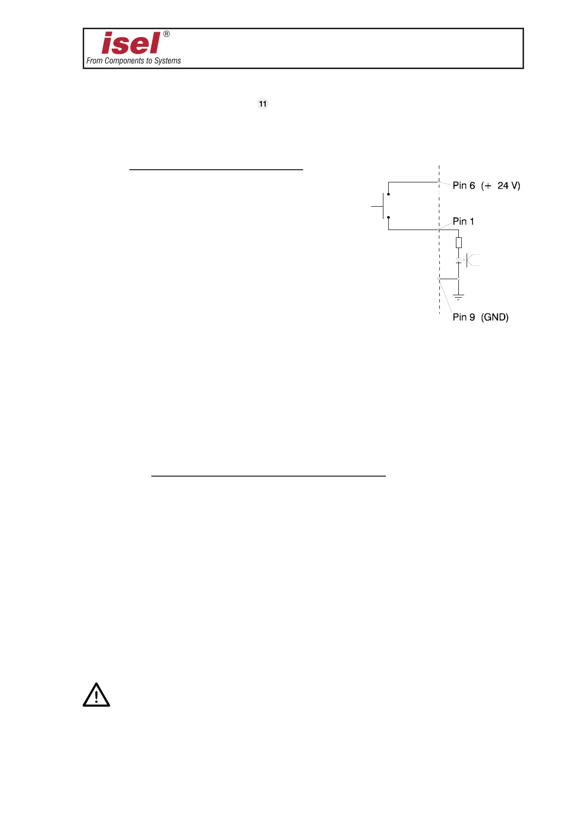
Use the 9-pin Sub D connector
(see image page 19). The input is carried out using an
optical isolator with the anode led outwards. The necessary series resistor is available on the
printed circuit board.
Connection example:
Pin Description
1 user input 2
2 user input 1
3 occupied
4 occupied
5 GND 24 V
6 + 24 V I/O voltage
7 occupied
8 occupied
9 GND 24 V
Use pin 6 for the 24 V control voltage of both inputs.
Pins already used by isel Germany must not be modified. Otherwise, the machine can
not function properly.
ÓÎäÊ6ÊÕÌ«ÕÌ\
Use the
➇➇
➇➇
➇ connector (see image page 19). /iÊViVÌÀÊV>ÀÀiÃÊÓÎäÊ6Ê«ÌiÌ>t
Terminal Description
1 230 V, live supply
2 switching output tooling machine
3 switching output 230 V OUT 3 (bit 3)
4 null tooling machine
5 null supply
6 null OUT 3
7 null OUT 4
8-
You can replace the pre-installed tooling machine on terminals 2 and 4 by another machine
(max. power approx. 900 W).
Additional 230 V loads must be connected to terminals 3 and 5 and/or terminals 6 and 8.
A maximum of 1 Amp (200 W) can be drawn from output 3.
ÊÓÎäÊ6Ê>`ÃÊ>ÀiÊÞÊÃ}i«iÊÃÜÌVi`°Ê9ÕÊÕÃÌÊ>ÃÃÕiÊÌ>ÌÊ>ÊÌiÀÀÕ«Ìi`
>`ÊÃÊÌÊiViÃÃ>ÀÞÊÛÌ>}ivÀii°
In addition to the fusing
➆ and ➈, all 230 V switching outputs (terminals 2, 3 and 8) are
protected by a common fuse at the power input.