Do you have a question about the Iskra MC350 and is the answer not in the manual?
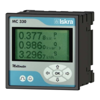
Details the application of Energy Meter MC320 and Multifunction Meter MC330.
Compares hardware features across MC320, MC330, MC350, and MC350H models.
Compares software functions across MC320, MC330, MC350, and MC350H models.
Lists basic measurements supported by the devices, categorized by phase, phase-to-phase, and energy.
Lists additional measurements supported, including MD values and frequency.
Describes RS232 communication for direct PC connection.
Describes RS485 communication for network connection of multiple devices.
Details MiQen software for monitoring, settings, analysis, and upgrading.
Sets passwords for access levels (L1, L2) and automatic activation time.
Allows setting 16 alarms in 2 groups, defining time constants, delay times, and hysteresis.
Details supported measurements based on device type and connection settings.
Describes different electric connection types (e.g., single phase, three phase).
Provides a table showing supported measurements based on connection mode and device type.
Provides accuracy classes for various measured values like current, voltage, power, and frequency.
States compliance with EN 61010-1 for voltage ratings and installation categories.
States compliance with EMC directives and EN 61326-1.
Explains Modbus and DNP3 protocols over RS232, RS485, or USB, and Modbus protocol specifics.
Details Modbus protocol for point-to-point and multi-drop communication, its open nature.
Lists Modbus registers for actual measurements, including parameter, type, and register ranges.
Explains DNP3 protocol for point-to-point and multi-drop communication over serial ports.
Details DNP3 protocol operation, enabling point-to-point and multi-drop communication.
Details Profibus DP-VO support for up to 32 slave devices at speeds up to 12 Mbps.
Explains the structure of input/output telegrams for data exchange between master and slave devices.
Details M-Bus communication settings via LCD screen: address, secondary address, and baud rate.
Explains command telegrams for initializing, selecting, and reading data via M-Bus.
Provides definitions for symbols used in calculations and equations.
Presents mathematical equations for voltage, current, power, and THD.
| Type | Digital Multimeter |
|---|---|
| Diode Test | Yes |
| Continuity Test | Yes |
| Power Source | 9V battery |
| Display | LCD |
| DC Current Ranges | 10A |
| Current Range | DC: 200µA to 10A DC |
| Battery Type | 9V |