Page 6
Installation manual
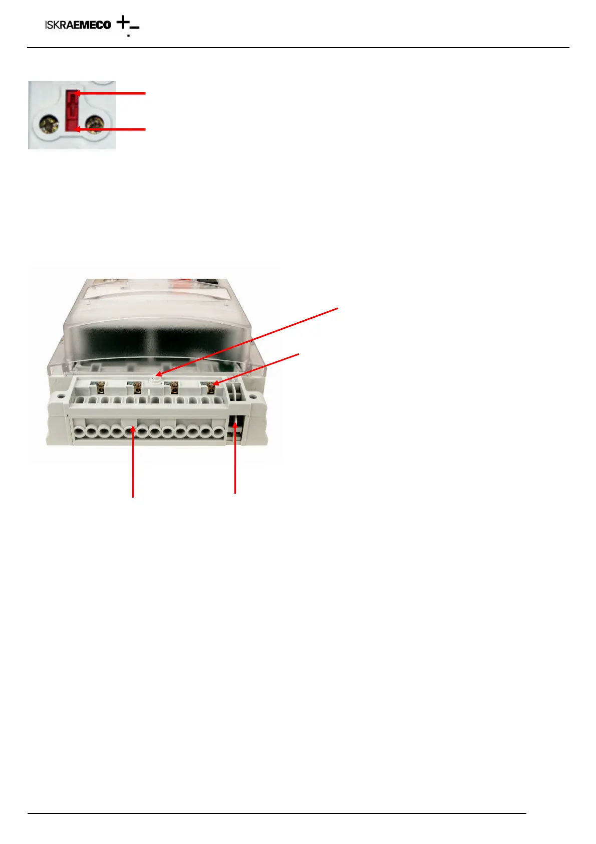
Closed – opened voltage link:
Fig. 5: Voltage link – direct connected meter
There are 6 auxiliary terminals on the meter basic board. They could be defined as inputs (max. 2), outputs (max. 4),
communication (CS or RS-232 or RS-485) and external power supply.
To access terminal block remove terminal cover (8, Fig. 1: Meter parts), fixed with two screws (9). Seals from screws
must be removed.
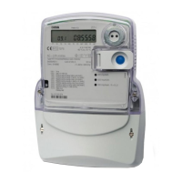
Voltage and current terminals Auxiliary terminals
Fig. 6: Terminal block – indirect connected meter MT830
MT831 meter (with input/output and communication module)
There are 6 auxiliary terminals on the meter basic board. They could be defind as inputs (max. 2) and external power
supply. Additional inputs and outputs are located in the module.
Sensor for terminal cover opening
Additional voltage terminal


 To Next Page