Do you have a question about the Isuzu 4LB1 and is the answer not in the manual?
Instructions for performing service operations on the engine.
Information on how the workshop manual is organized and presented.
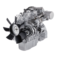
Visual depiction of engine models and their external parts.
Key technical specifications and data for engine models.
Torque values for various bolts and fasteners used in engine assembly.
Procedure for tightening nuts and bolts using angular rotation.
Specific torque values for major engine components.
Identification of locations where gaskets are used on the engine.
General maintenance procedures and guidelines for the engine.
Guidance on selecting appropriate engine oil based on viscosity and ambient temperature.
Procedures for taking apart the engine components.
Steps for inspecting and repairing engine parts.
Steps for putting the engine components back together.
Diagram illustrating the flow of lubricating oil through the engine.
Details on the inspection, replacement, and clearances of the oil pump.
Diagram showing the path of cooling water circulation in the engine.
Procedures for disassembly and reassembly of the water pump.
Inspection and replacement guidelines for the engine thermostat.
Diagram illustrating the fuel flow path within the system.
Structural drawings and notes for governor assembly and adjustment.
Procedures for disassembly, inspection, and adjustment of nozzle holder assembly.
Troubleshooting steps for engine starting failures.
Diagnosis and solutions for irregular engine operation.
Guide to identifying and resolving abnormal exhaust gas conditions.
Troubleshooting steps for battery over-discharge and related electrical faults.
Diagnosing and fixing low engine power and overheating.
Troubleshooting low oil pressure and high oil consumption.
Identifying causes and solutions for abnormal engine knocking.
Catalog of specialized tools required for engine maintenance and repair.
Tables for converting various units of measurement for engine specifications.
| Cylinder Arrangement | In-line |
|---|---|
| Number of Cylinders | 4 |
| Displacement | 2.8 L (2771 cc) |
| Fuel System | Indirect Injection |
| Cooling System | Water-cooled |
| Aspiration | Naturally Aspirated |
| Fuel Type | Diesel |
| Bore x Stroke | 93 mm x 102 mm |
| Engine Type | 4-Cylinder, 4-Stroke Diesel Engine |