GENERAL INFORMATION
1-3
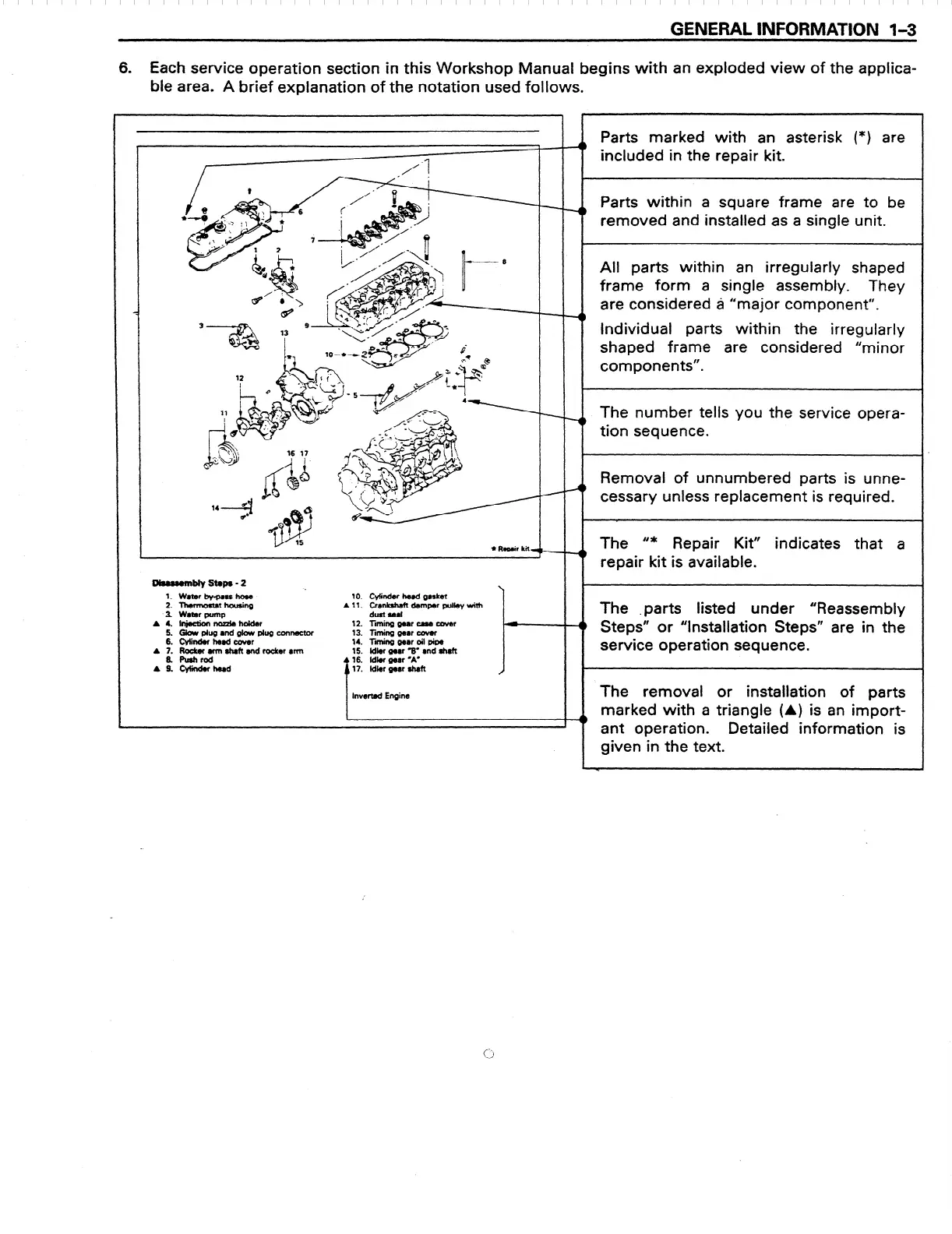
6. Each service operation section in this Workshop Manual begins with an exploded view of the applica-
ble area. A brief explanation of the notation used follows.
o&sumblystaps-2
-.
1. W8terby-passho8e
2. ThwmosUtfiou8ing
.3. WatDrpfJmp
A 4. l~rKuzleholder
5. Glow plug and gJow plug connector
6. cylllherdcowr
A 7. Rocbrarmshaftandrockerrrm
S. fbhrod
A 9. c-w
10. Cylinder he8d gultet
A 11. Crankshaft damper pulley with
dust seal
12. liming gear cue cutter
13. liming gmr cover
14. Tf gear oil pipe
15. ldktr gear 3. rnd shaft
16. ldbr war -A’
l?. Mkr gear shaft
I
lnvwted Engine
I-
Parts marked with an asterisk (*) are
included in the repair kit.
Parts within a square frame are to be
removed and installed as a single unit.
All parts within an irregularly shaped
frame form a single assembly. They
are considered ti “major component”.
Individual parts within the irregularly
shaped frame are considered “minor
components”.
The number tells you the service opera-
tion sequence.
Removal of unnumbered parts is unne-
cessary unless replacement is required.
The ‘I* Repair Kit”
indicates that a
repair kit is available.
The .parts listed under “Reassembly
Steps” or “Installation Steps” are in the
service operation sequence.
The removal or installation of parts
marked with a triangle (A) is an import-
ant operation.
Detailed information is
given in the text.
 Loading...


