I&!.-
,
1” GENERAL INFORMATION
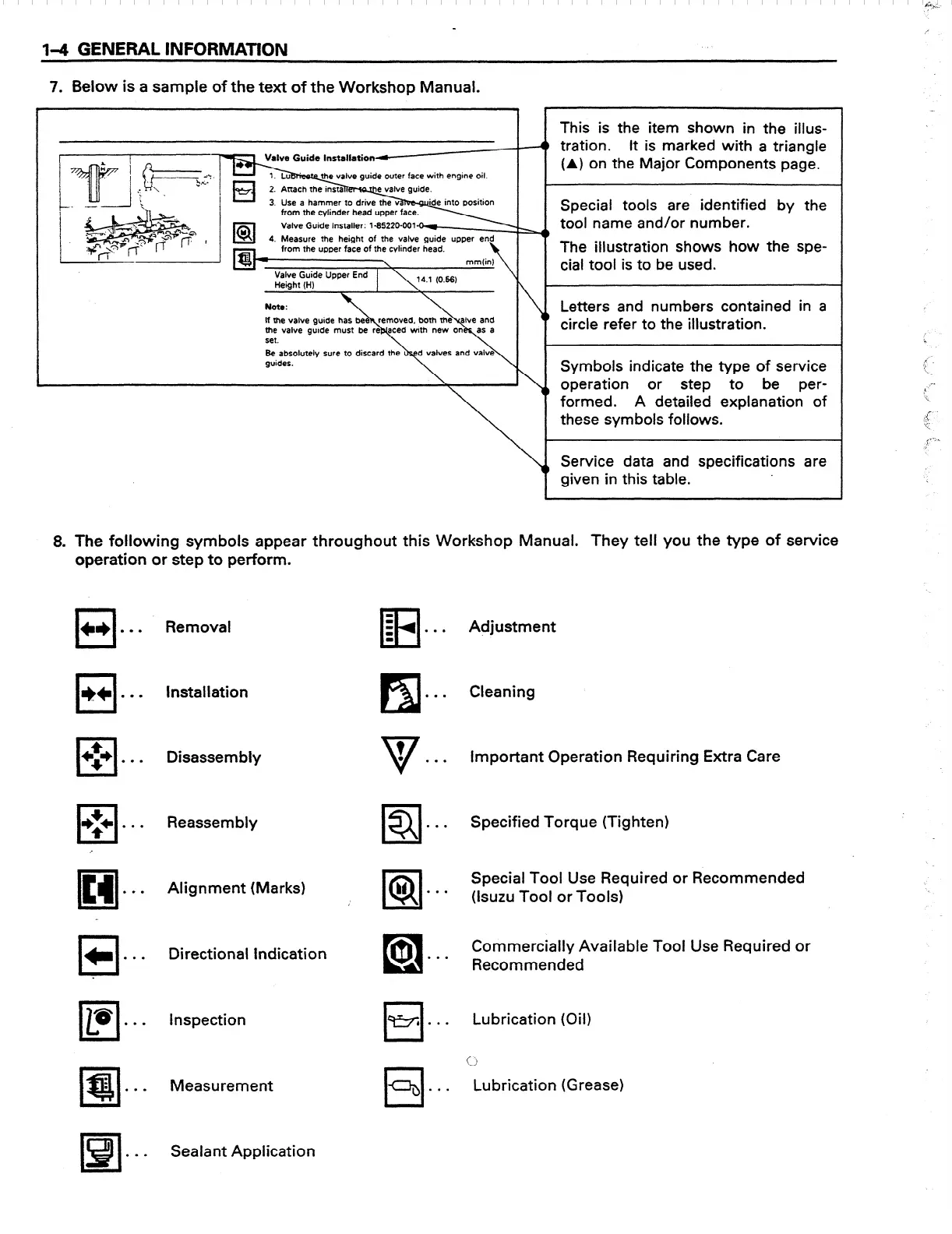
7. Below is a sample of the text of the Workshop Manual.
This is the item shown in the illus-
4 tration. It is marked with a triangle
(A) on the Major Components page.
Special tools are identified by the
from the upper face of the cylinder head.
Letters and numbers contained in a
circle refer to the illustration.
set.
guides.
Symbols indicate the type of service
or step to be per-
formed. A detailed explanation of
these symbols follows.
Y
Service data and specifications are
given in this table.
8. The following symbols appear throughout this Workshop Manual. They tell you the type of service
operation or step to perform.
q
CI)
. . .
0
*+ l **
III
+$+ . . .
cl
$+ l l l
ltrl
. . .
0
*
. . .
El
aB
. . .
.
.
l!!il
.
. . .
B!l
. . .
Removal
Installation
Disassembly
Reassembly
Alignment (Marks)
Directional Indication
Inspection
Measurement
Sealant Application
-
El
D
II)
. . .
l5l
. . .
V
?
0
. . .
m
.
. .
El
bl
.
. .
cl
0
. . .
0
qy5 l l l
cl
-b
. . .
Adjustment
Cleaning
Important Operation Requiring Extra Care
Specified Torque (Tighten)
Special Tool Use Required or Recommended
(lsuzu Tool or Tools)
Commercially Available Tool Use Required or
Recommended
Lubrication (Oil)
(2
Lubrication (Grease)
 Loading...


